|
1ST QTR 2003
|
 •
•
 •
•
 •
•

|
| DATE |
HRS |
TTD |
ACTION |
IMAGES |
| 01/08/03 |
8.0 |
540.5 |
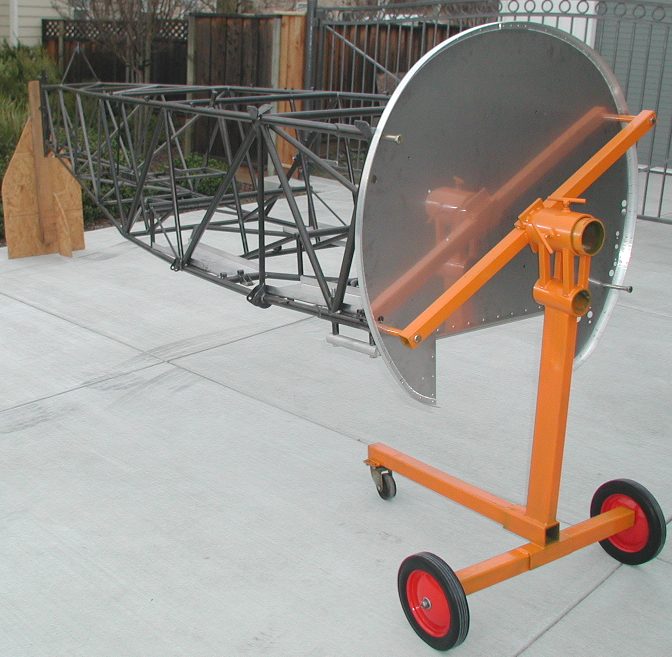
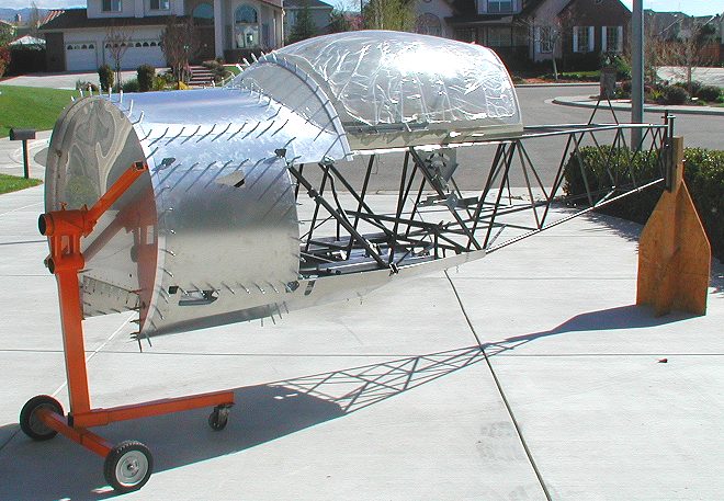
Modified my engine stand to hold
the fuselage by two of the motor mount holes, so I can get the firewall on
and start fitting sheet metal and formers. I also made the stand hold the
fuselage up higher, and use bolts to hold it in any position. I wish I had
done this BEFORE I started the finish welding, it sure would have been
nice. |
 |
 |
 |
| 01/11/03 |
1.3 |
541.8 |
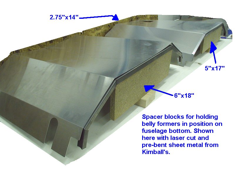
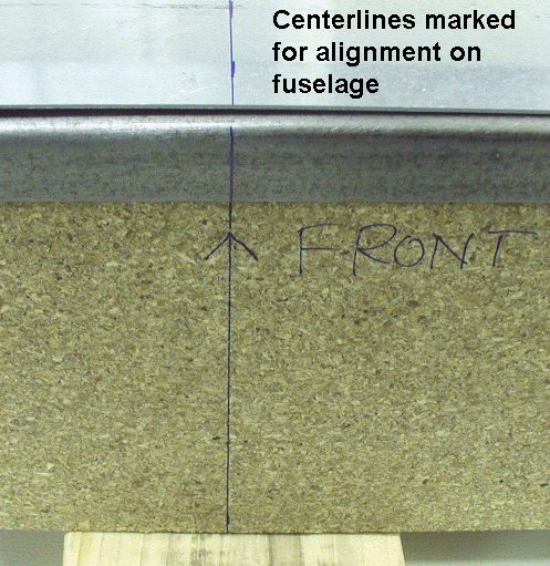
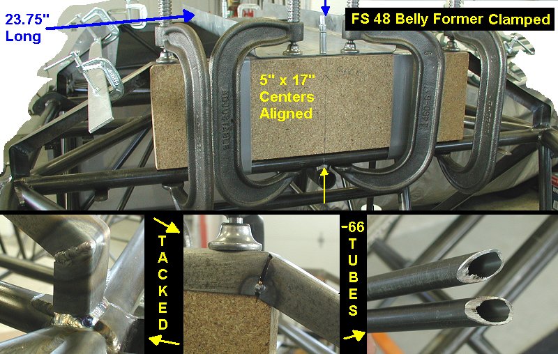
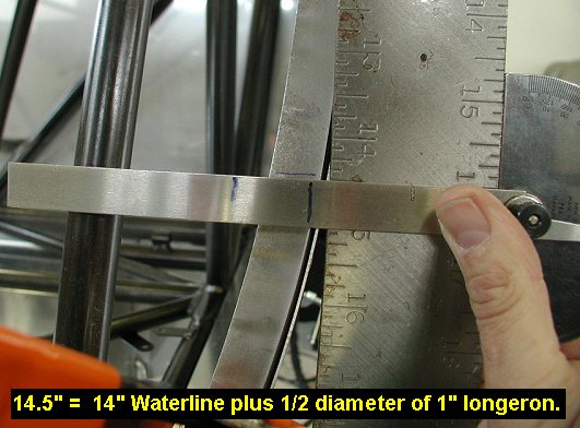
Cut some 3/4" thick
particle board blocks to hold belly formers at proper height above
crossmembers. Marked centerlines on sheetmetal, formers and blocks so that
I can line them up on the crossmember tube centerlines. Block dimensions
are: FS 24.9 = 6"x18", FS48.0 =
5"x17" and FS75.75 = 2.75"x14". |
 |
 |
| 01/14/03 |
1.5 |
543.3 |
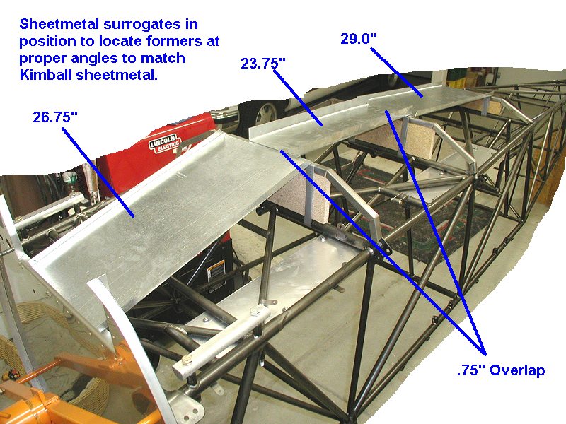
Cut some sheetmetal surrogates
to put in place of sheetmetal panels, since I can't get access for welding
with the aluminum panels on. Surrogates are 26.75", 23.75" and
29.0" long as you go aft from firewall. Discovered
I might have to modify the blocks for better fitting and welding access
for the support tubes. |
 |
| 01/21/03 |
7.5 |
550.8 |
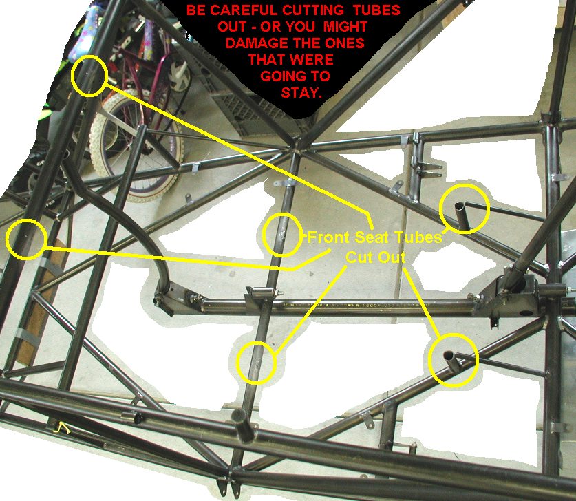
Back on the 19th my friend Phil
came over and sat in the front seat and l discovered he wouldn't fit in
there with the canopy closed (he's 6'5" but sits really tall) so I
decided to design and install a new lower front seat, with the intention
of using cushions for shorter people as needed. I spent a good 4
hours plus designing the new seat, torque tube action below had to be
considered. I also consulted the guru Kevin Kimball before finally
deciding on a modification. Finally today I took out my cutoff wheel,
dremel tool and hacksaw blade and cut out the front seat. I then carefully
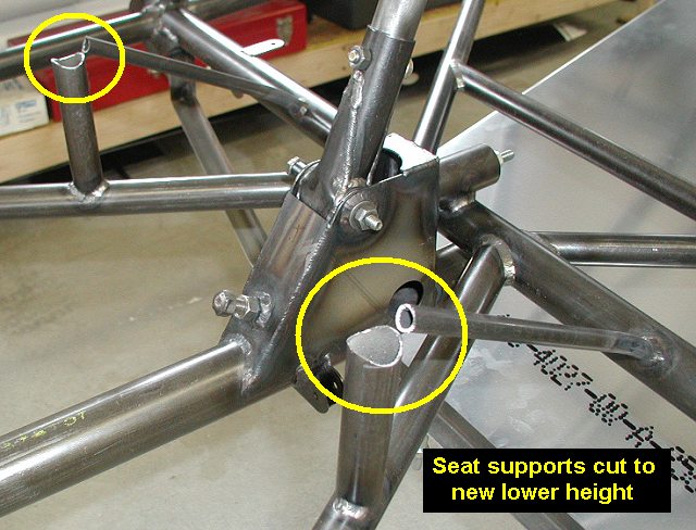
cleaned up the tubes of excess weld. I was able to save the forward
1" seat crossmember, and drop its vertical supports about 1.5"
or so. See the drawing. Another interesting fact: I thought the front seat
was all done before this, but I discovered that I had forgot to put the
horizontal crossmember in between the seat back tubes!! It won't be
forgotten again. |
 |
 |
 |
| 01/22/03 |
3.4 |
554.2 |
Cut and fit tubes for the new seat. Heated
and bent the short 3/8" diameter 210-68 tubes down to the height of
the new 1" crossmember. This time I got SMART, and drilled tiny holes
in the joints of the tubes for pressure relief during welding. I remember
the blowouts really pissin' me off the first time I welded the seats up. |
 |
 |
| 01/23/03 |
1.6 |
555.8 |
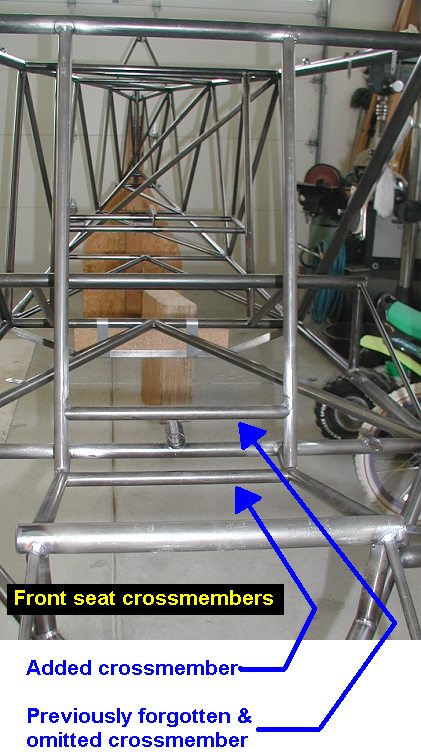
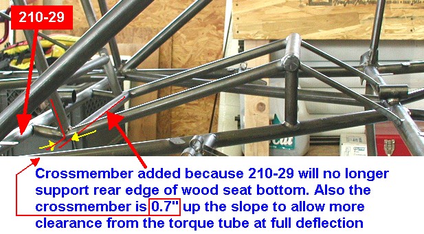
Cut and fit 2 new rear seat crossmembers out
of 3/4-.035 tube. With the new design, I needed to add one since the seat
bottom drops a bit before angling up to the fwd 1" crossmember. So I
needed to add a tube to support the wood seat bottom. Damn, more weight!!!
Ah, the cost of taking friends flying....Tacked the tubes in. Also note
that the seat bottom crossmember is slightly forward (up the seat slope)
from the angle joint so it will have adequate clearance with the torque
tube with full aileron input. |
 |
 |
| 01/26/03 |
3.4 |
559.2 |
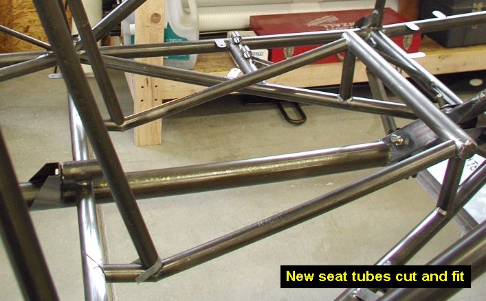
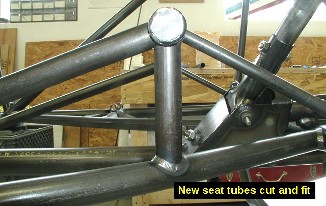
Finished welding up the new seat tubes. No
blowouts, easy welding. |
| 02/01/03 |
2.5 |
561.7 |
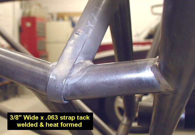
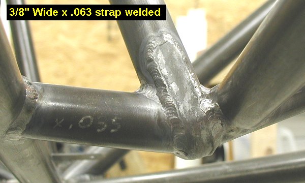
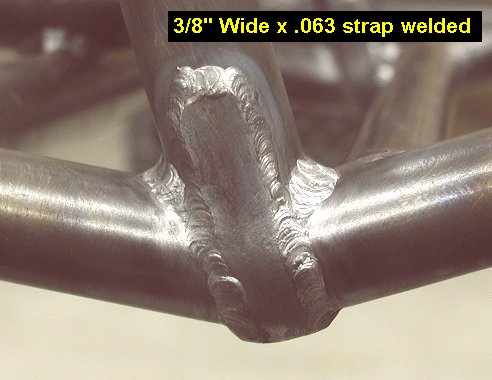
Cut and welded in some 3/8 wide strips of
.063 for strapping around the bottom of the angle joints the seat now has.
This was suggested by Kevin to make the joint stronger. It sure looks
strong now too. I heat formed the straps around the bottom of the joint
too for better fit and welding. |
 |
 |
 |
| 02/03/03 |
1.5 |
563.2 |
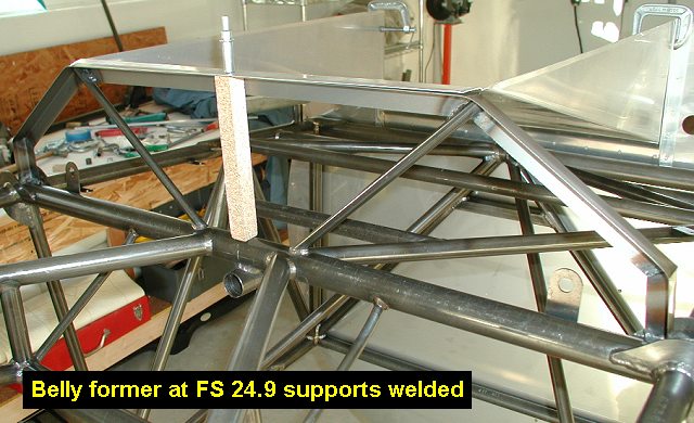
Cut, fit and welded the 210-66
belly former support tubes at FS 24.9. Did some setup for the former at FS
48.0. HINDSIGHT FROM 3/10/04: Install the 210-105 Aileron Stop Bushings
before this step to allow easier welding of the bushings. Skip ahead to
see build log from 1st Qtr 2004 |
 |
| 02/04/03 |
4.3 |
567.5 |
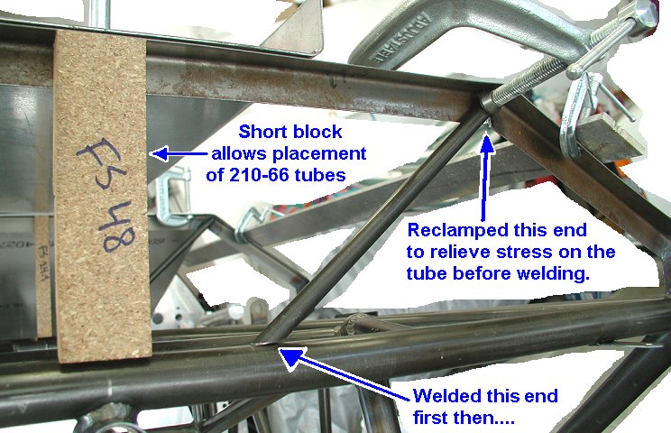
Setup belly former at FS 48 with 5x17 block
of particle board and sheetmetal surrogate cleco'ed in place. Checked
alignment then clamped in position. Tackwelded the ends to the longerons,
then tacked the mitered joints. Took out the 5x17 block and put a 5"
short block in its place. Cut and fit the 210-66 tubes, then clamped them
in place on the former. I then tack and finish welded the joints of the
-66 tubes to the 210-29 crossmember BEFORE tack welding them to the belly
former. I then released the clamp and retightened it which allowed the -66
tube to relax the stress before welding to the former. I didn't do this on
the FS24.9 former and had to whack it with a hammer & block a few
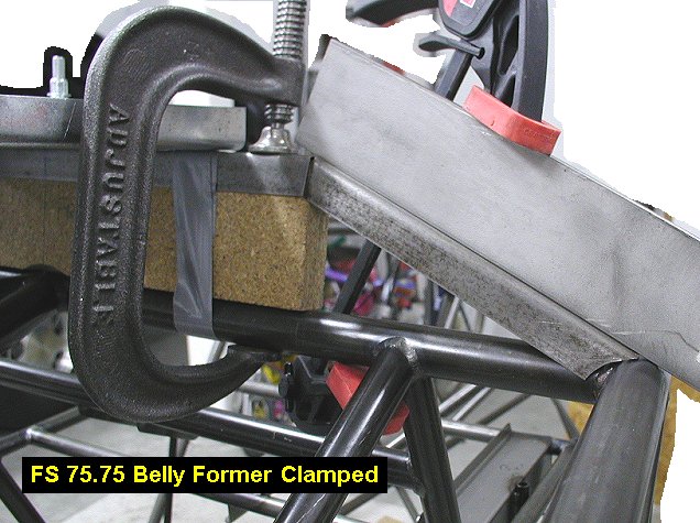
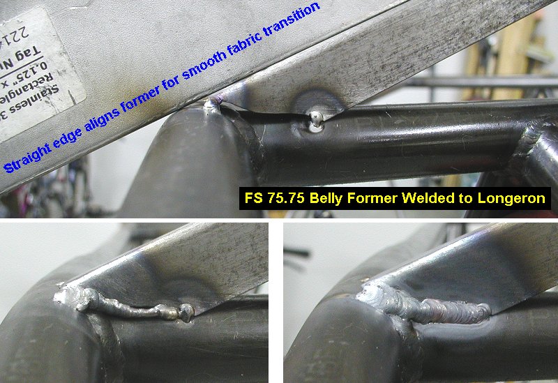
times to straighten it out afterwards. After completing the FS 48 former I
setup and welded the FS 75.75 former to the longerons and tacked the
joints. Note that I used a straight edge when tacking this former to the
longerons to assure a nice fabric transition there later. I then replaced
the big 2.75x14 block with a short 2.75 block, leaving it ready for the
standoffs to be put in next. |
 |
 |
 |
 |
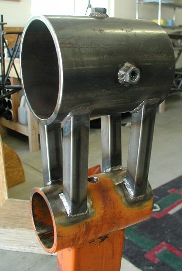
| 02/04/03 |
3.0 |
570.5 |
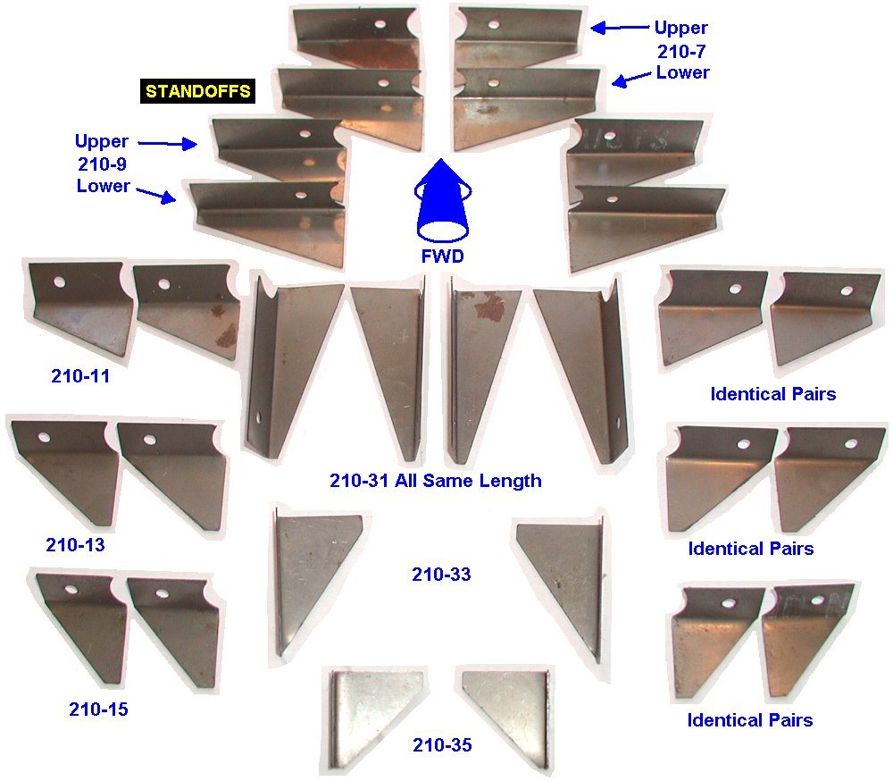
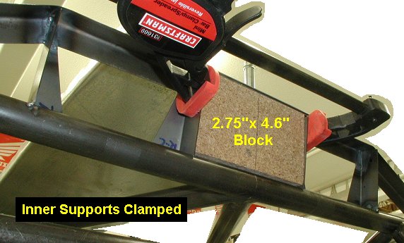
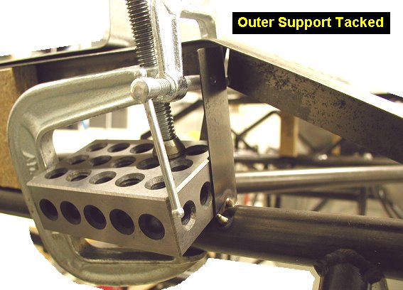
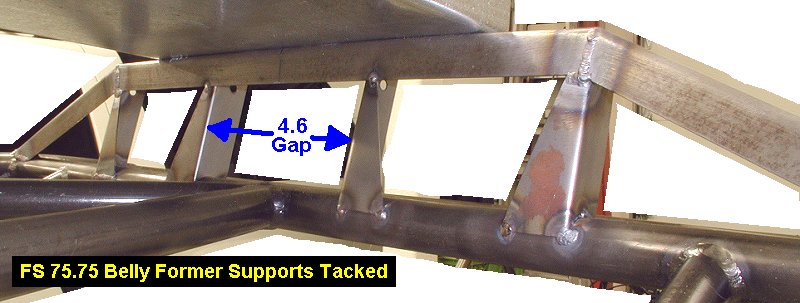
Since I knew I was going to need four, I got
out all the laser cut and bent standoffs that I got from Kevin, so I could
figure out which ones go where. It took a bit of time using pictures from
my website to help identify location and orientation of them. Once I did
so, I made a picture to help me keep track of
them in the future. Since Kevin uses 4 standoffs at the FS 75.75 belly
former, I had to figure out the spacing. Using a picture I had shot
earlier of a Kimball fuselage, I estimated the center gap to be about 4.25
inches. Since I had a block of wood already cut to 4.6 I used it to set
the center gap. I didn't want to use less gap, since I was concerned about
elevator pushrod side movement during full aileron application. I then
tacked the 4 supports into position. |
 |
 |
 |
 |
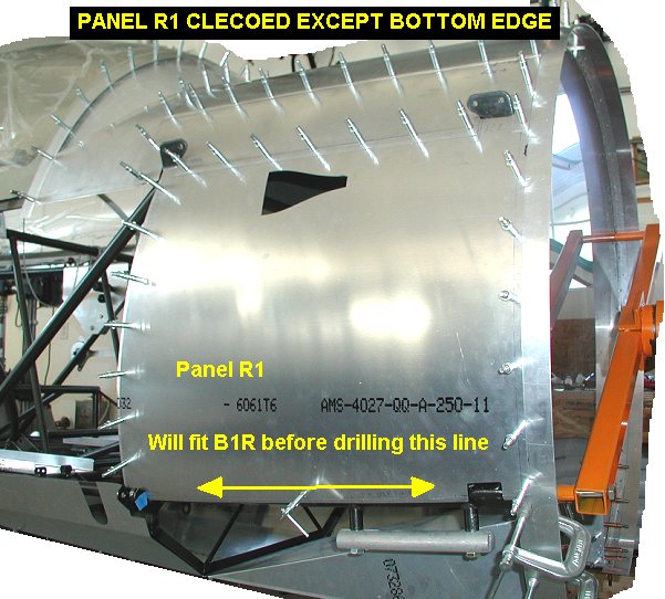
| 02/11/03 |
1.2 |
561.7 |
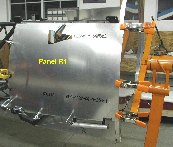
Tack welded a 210-104 fairing
angle onto the upper right longeron between FS 0 and FS 22. Clamped and
test fit the R1 (forward right side) panel into position. Sent a request to
Kevin Kimball for advice on fitting it. |
 |
 |
| 02/12/03 |
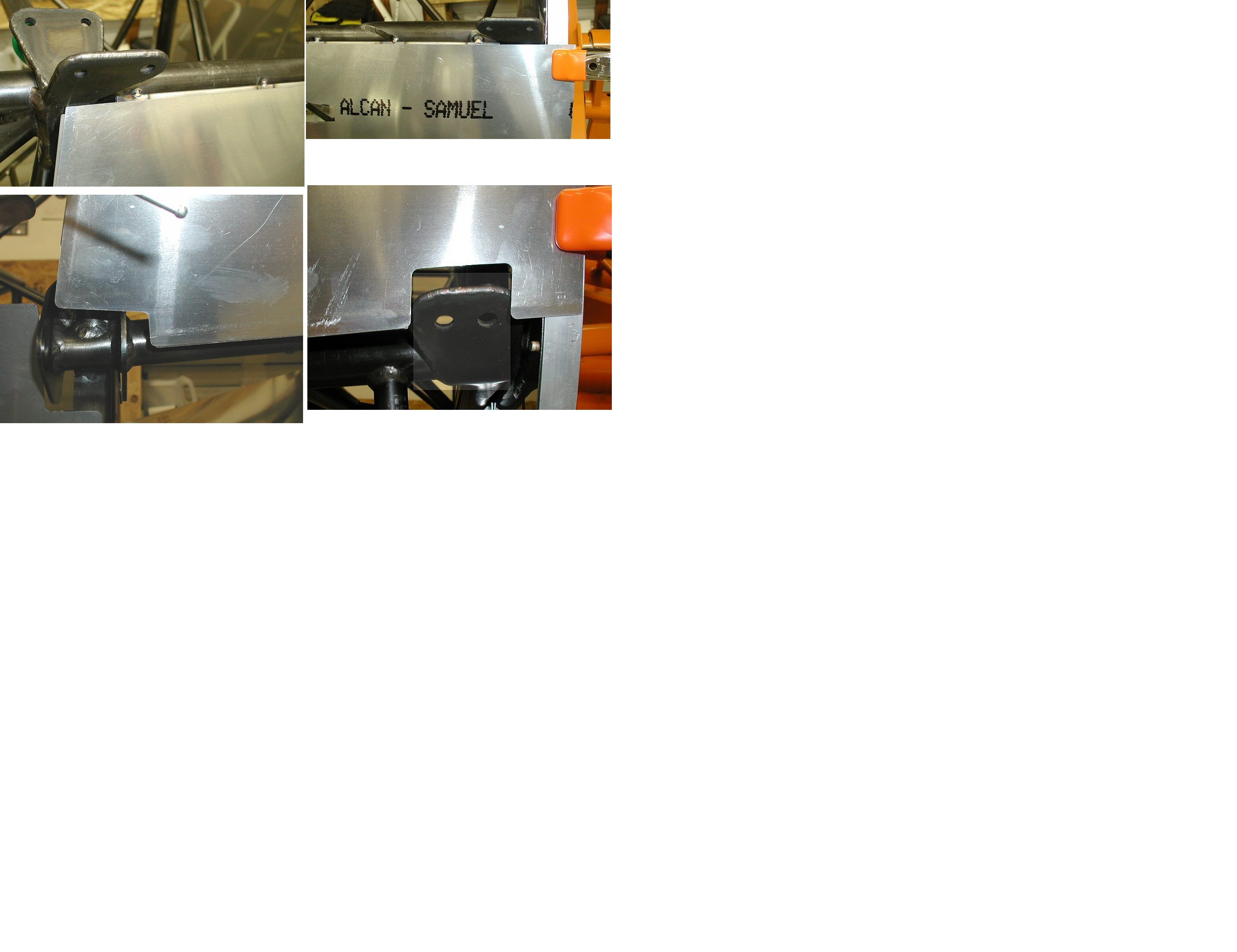
1.2 |
561.7 |
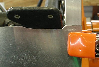
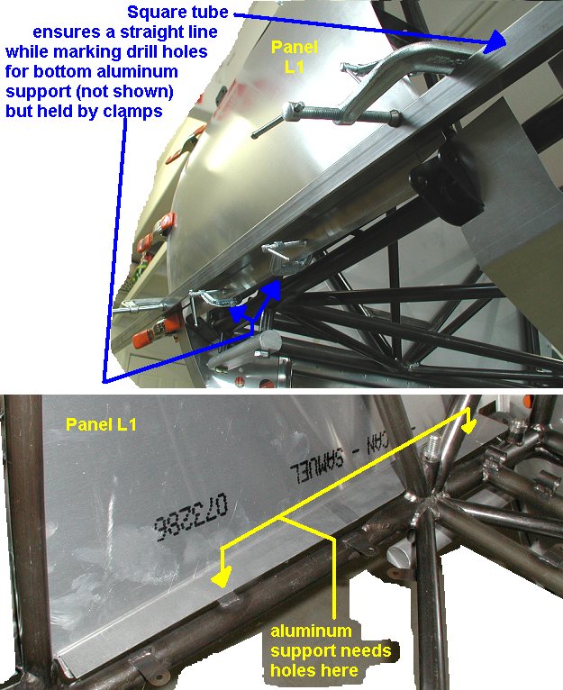
Readjusted the fit of the R1 panel to square up with the firewall angle. Had to trim the panel a little
bit around the forward cabane fitting. Tack welded the steel former on the
right 210-7 tube. Inserted the firewall ring for spacing between the
firewall 226-3 angle and the panel, then marked locations for holes in the
bottom aluminum attach angle. I drilled the holes and attached it to the
two tabs welded on the bottom longeron. Tack welded the upper fairing
angle on the left top longeron forward section. Test fit and trimmed the
L1 panel pretty much the same as the right one. |
 |
 |
 |
 |
| 02/13/03 |
2.9 |
564.6 |
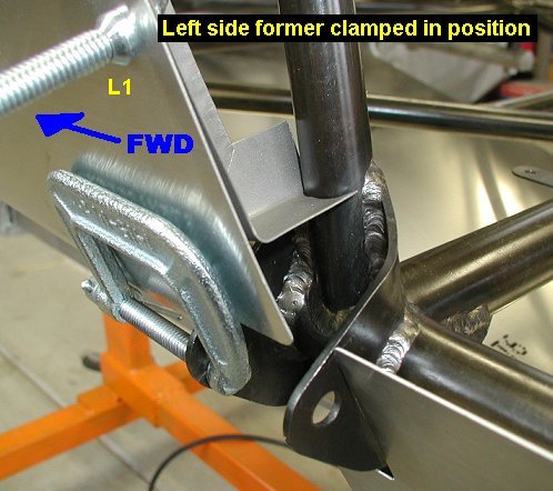
Tack welded the left former to the left
210-7 tube. Welded up both of the formers along the 210-7 tubes. Skip
welded the fairing angles to the upper longerons. Located, drilled the
bolted the lower left aluminum angles to the two tabs on the lower left
longeron. Marked lines for screws on bottom and top edges of panels. |
 |
 |
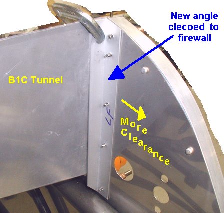
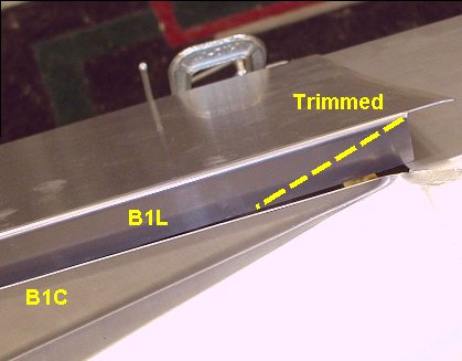
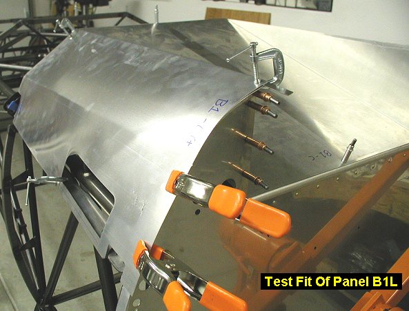
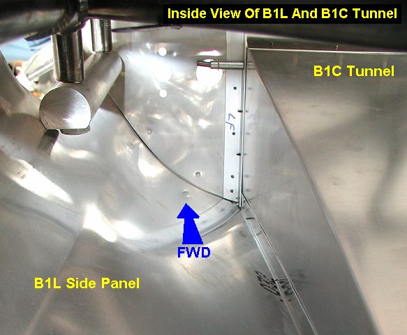
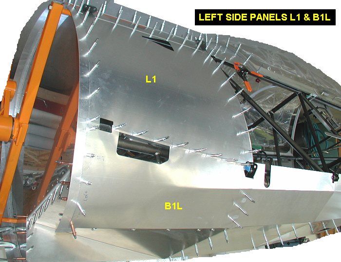
| 02/16/03 |
1.5 |
566.1 |
Since the B1C (bottom tunnel)
sheet metal is just a
little wider than the angles riveted to the firewall, I drilled out the
rivets and removed the two firewall vertical aluminum angles, 226-3. I
then made new angles from some 3/4 x 3/4 x 1/16 aluminum angle I got down
at the hardware store. Its not the 6063 specified in the plans but should
work just fine in the little short sections I'm using at that location. I
drilled and clecoed them into position. The tunnel now fits good and will
install easy with the two side panels (B1L & B1R) riveted to it. I trimmed and
test fit the B1L lower panel to the tunnel. |
 |
 |
 |
 |
|
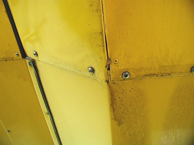
NOTE: DURING
SHEET METAL INSTALLATION I WILL BE USING A SLIGHTLY DIFFERENT SCREW
SPACING FOR EACH DIFFERENT SCREWLINE. This is done so that
screws will be spaced evenly among their neighbors for each section of
panel, of which they are ALL slightly different in length and number of
screws. The idea is to have an OVERALL pleasing screw layout, with no
glaring variations of spacing catching the eye. Hopefully I will be
successful !!!!! I calculate the spacing for each section of
screws by dividing the screwline distance by a whole number that results
in the closest to 3" spacing. I expect my spacing to vary between
2.75" and 3.25" on-center screw spacing. Also, see my Sheetmetal
Hardware List.
|
| 02/17/03 |
0.6 |
566.7 |
I trimmed and test fit the B1R lower panel to the tunnel. |
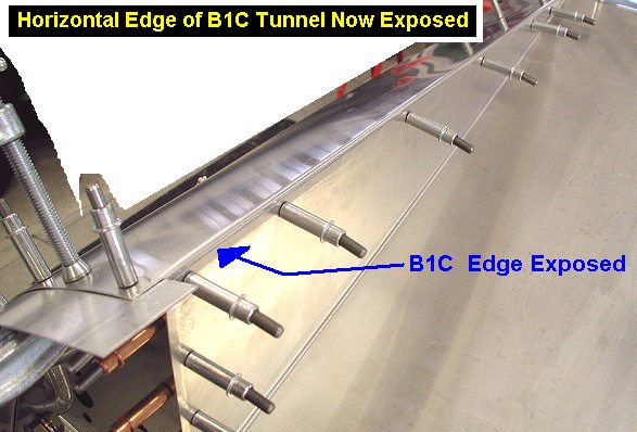
| 02/18/03 |
3.0 |
569.7 |
Drilled and clecoed the fwd and aft edges of
the B1C tunnel. Drilled and clecoed the fwd and aft edges (not the angled
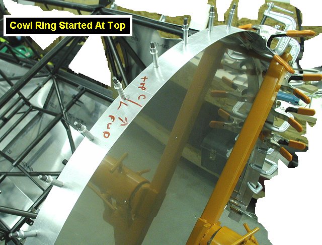
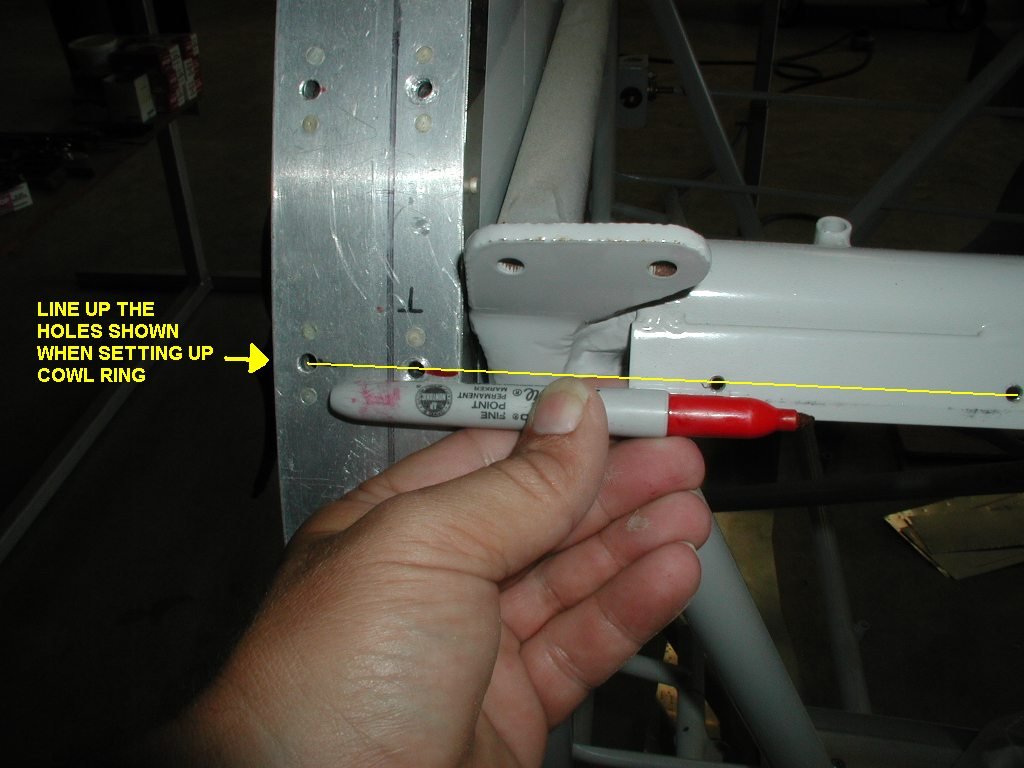
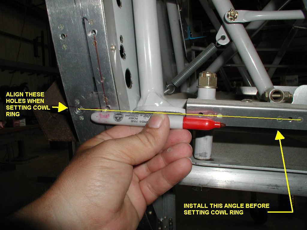
sections though) of the other two bottom panels. Deburred the cowl ring,
and clamped it in position on the top center of the firewall. I then
clamped, drilled and clecoed the upper holes, being careful not do the
holes near the joint of the top panels so I can later fudge the hole spacing
a little if needed to make it look nice. My strategy was to work the cowl
ring from top center around to the bottoms and also drill as many holes
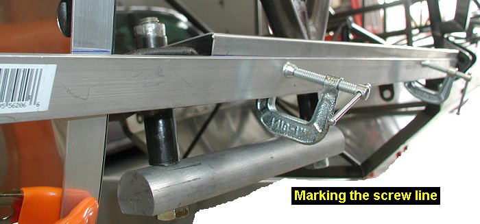
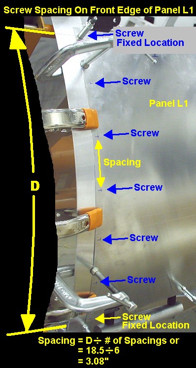
with the panels attached to avoid hole alignment problems later. I then attached the L1
panel and marked where the screw lines for the UPPER
and LOWER longerons
will go. I then calculated the rivet spacing (3.08) needed to get approx 3"
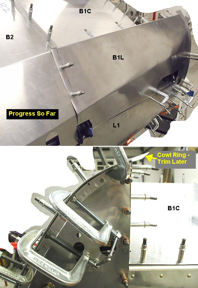
spacing but still be even for good appearance - see picture. I then marked, clamped, drilled and clecoed down the
front edge of the L1 panel, locking it in position with the cowl ring and
firewall angle. I then drilled and clecoed B1L onto B1C and then drilled and
put 2 clecos in the aft edge of B1L to the belly
former. I then figured out the spacing for the front edge of B1L (2.83,
the difference is not noticeable) and put clecos in the front
edge of B1L, cowl ring and firewall angle. |
 |
 |
 |
 |
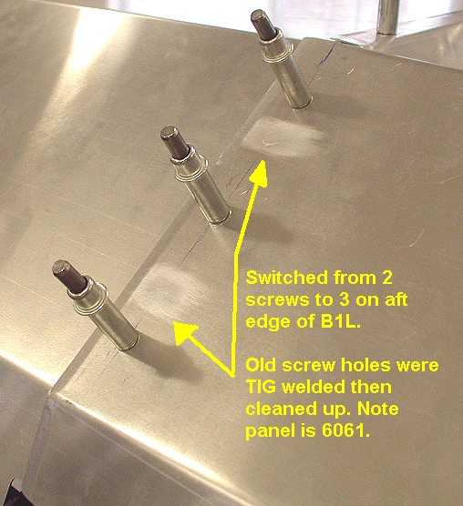
| 02/19/03 |
0.8 |
570.5 |
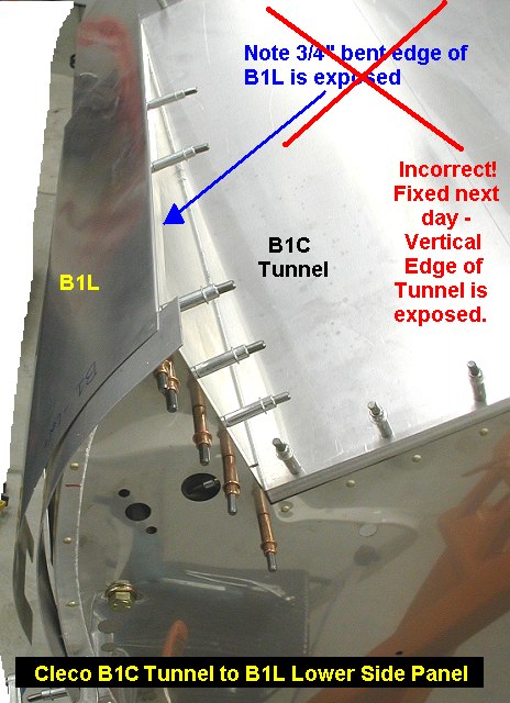
Discovered that I had
misunderstood the the B1C and B1L joint relationship and had them together
the wrong way, (see a pic of N360KC
for the right way), so I relocated B1L. While I had the B1L panel off I
decided to use 3 screws to hold aft edge down better, so I welded up the
two holes I had drilled and smoothed them out with a dremel. Its nice that
Kevin uses 6061 for the panels and I can weld up any mistakes. Re-attached
the panel and re-drilled the holes, which were slightly off after moving
the panel a little. |
 |
 |
 |
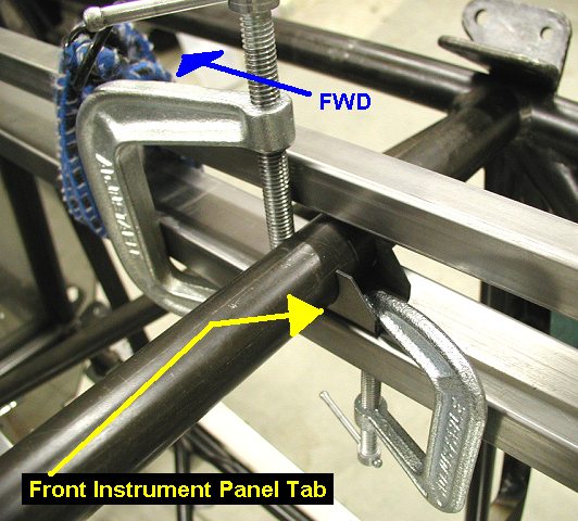
| 02/23/03 |
1.6 |
572.1 |
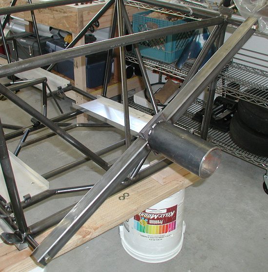
Installed the 3 front instrument panel tabs
onto the 210-40 crossmember. There are 3 of them, 1 on centerline, then
the other two are 11.0" either side of center. The jig I used to hold them was
just 2 lengths of square tube bungeed togther. It was a bit ugly
but worked well, it held the bottoms of the tabs level, while the
clamps kept them from moving out from being tight on the crossmember. |
 |
| 02/24/03 |
2.2 |
574.3 |
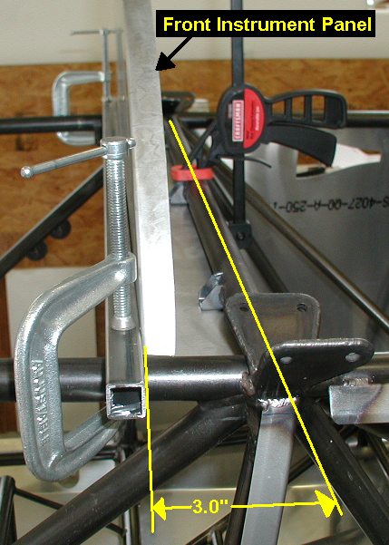
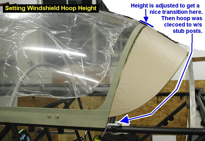
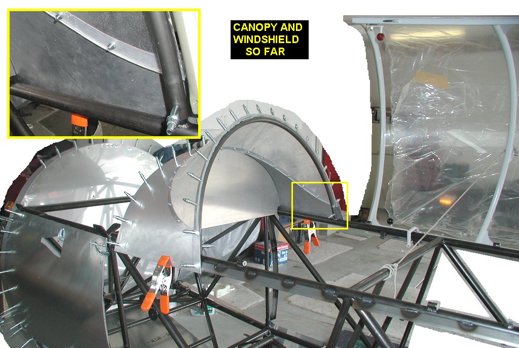
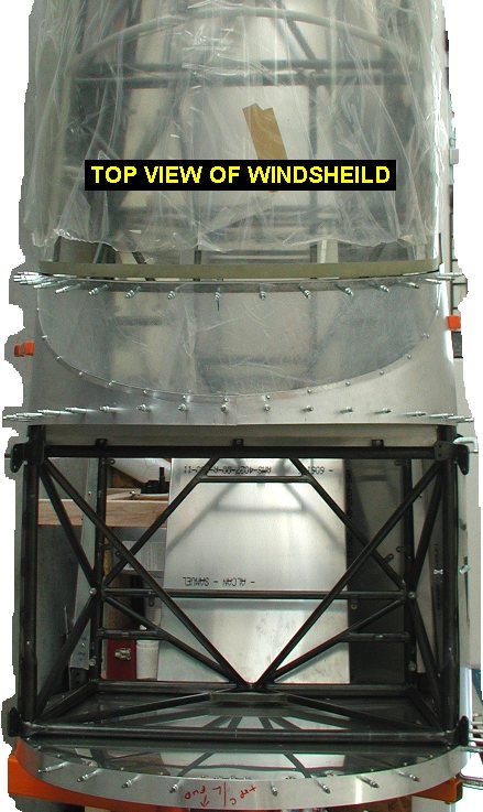
Found out from Kevin that the canopy
instructions state the need to install the front windshield (w/s) along with the
front instrument panel, so now I'm working on that. I usually like to
complete on section at a time, but now I'm skipping all over the place.
I'm sure when I get it all finished I'll come up with a really good plan
on how I should have done it, but that don't help me now! Anyway, I
mounted the bottom of the front inst panel so the rear face of it is
3" from the crossmember C/L. I then put the delrin bushings in the
fuselage bushings, then put the canopy on. Then I got the canopy hoop to
fit by trimming the ends of it a bit, and also bending the stub posts just
a little to allow the hoop to follow the canopy contour. I bent the stub
posts by slipping a thick wall tube over them and making small bends. Then I test fit
the front windshield. Note that I'm going to try a "flat wrap"
front w/s that I got from my friend Jimmy who made 2 when he was making
one for his airplane. |
 |
 |
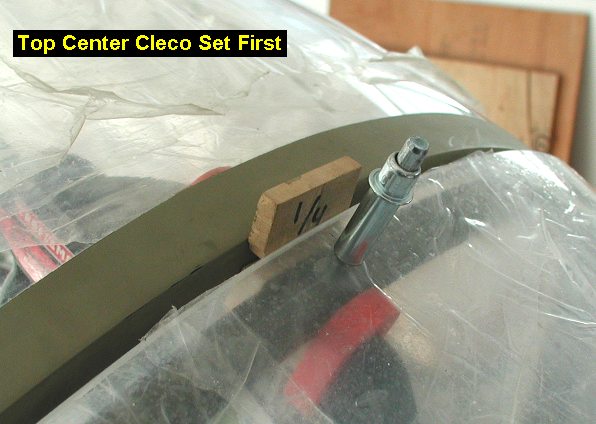
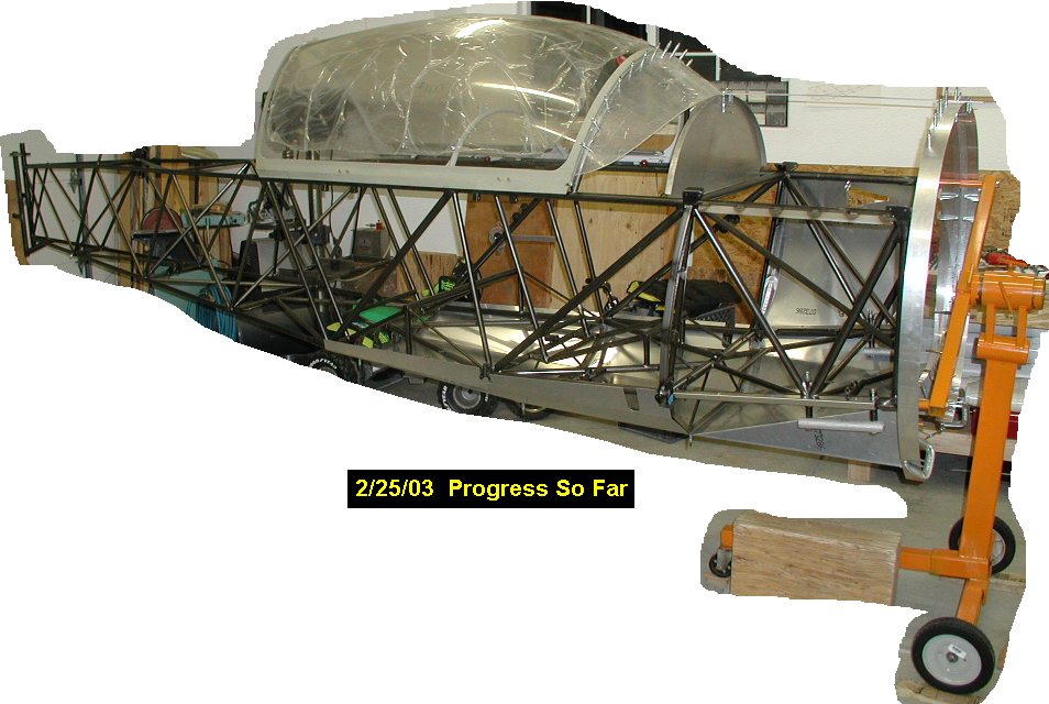
| 02/25/03 |
5.4 |
579.7 |
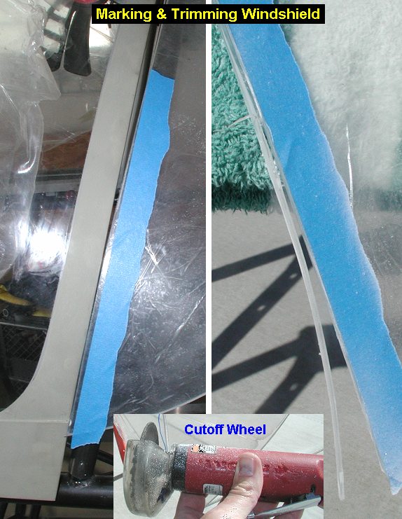
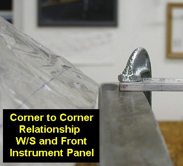
Replaced the paper
on the windshield (w/s) with plastic. Fitted the w/s as per Kevin's canopy
instructions, which basically says to trim the w/s as needed so that with
an even 1/4" spacing with the canopy, the w/s meets corner to corner
with the front instrument panel so the sheet metal side corners will fit.
I will probably have to adjust the angles on those metal parts where they
fit the w/s, since the flat wrap is at a slightly more raked angle. I
marked the areas to trim away and used my cutoff wheel to cut the w/s
which worked very well, even with the standard metal cutting disk. I just
used high rpm and very light pressure, and it made very clean cuts. It
took several trims to get it where I wanted since I didn't want to cut too
much off at once. I then marked, drilled #40 and installed a 3/32 cleco in
the top center of the w/s into the hoop. Then I put more clecos into
the w/s and hoop, working out from the center. I used a #40 drill that I
had dulled just a little with an abrasive disk, so it wouldn't be too
sharp, catch in the plastic while drilling, and cause a crack. I used a
sharp #40 for the hoop though. |
 |
 |
 |
 |
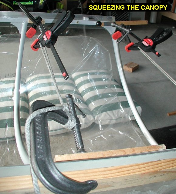
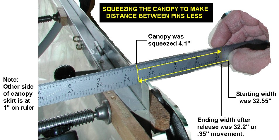
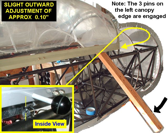
| 02/28/03 |
2.4 |
582.1 |
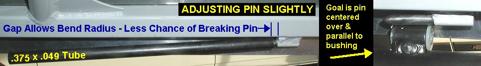
I discovered that
the canopy pins were too wide at the front, and I would never be able to
fly solo without someone up front to pull the canopy sides together to
close the canopy. So...by taking my time and carefully experimenting in small increments,
I squeezed the canopy and its frame closer together at the front which
allows both front pins to engage right in the centers of their bushings.
Using a bunch of clamps, blocks of wood and rope, I eventually squeezed
the canopy a little over 4 inches to get .35 adjustment, of which I then
widened back out .10" later to get a net movement of .25". Next
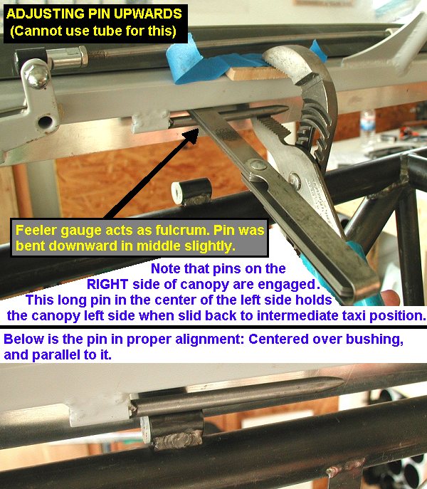
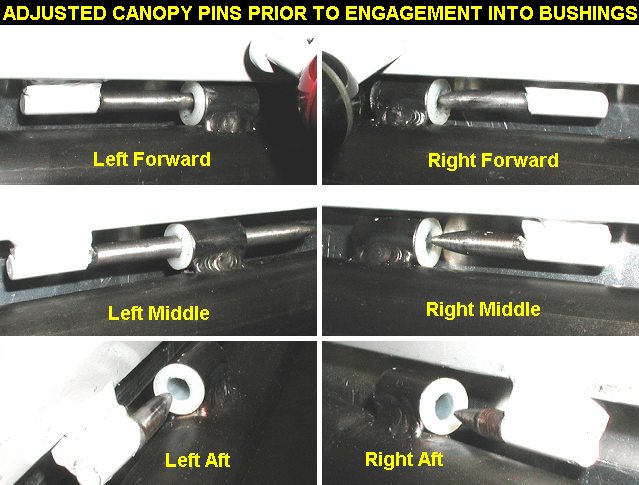
I adjusted the alignment angles of the pins on the right side by putting
the canopy in position with only the left pins engaged, which allowed me
to see and adjust the pins on the right side. I adjusted them so they were
parallel to the bushing both left/right and up/down. I then engaged the
right pins and adjusted the left pins. The canopy worked pretty well but
was still a little tight when fully latched, so I removed the dried grease
that was on the pins and bushings. After polishing the pins with 600 grit
sandpaper, I then sprayed just a little bit of silicone lubricant on
the pins & bushings. The canopy engages and latches easily and slides
back pretty well too. |
 |
 |
 |
 |
 |
 |
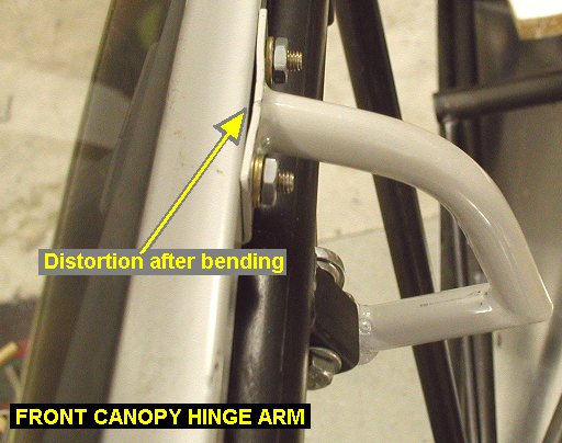
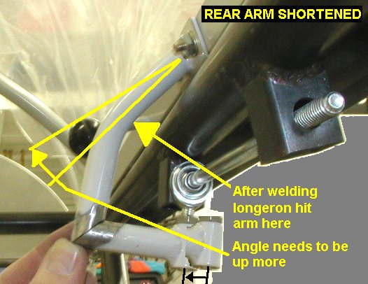
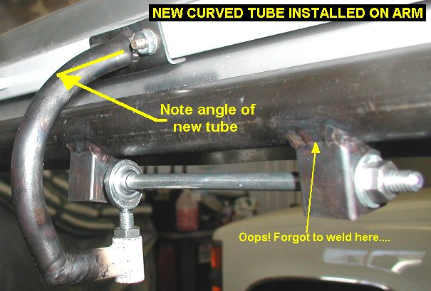
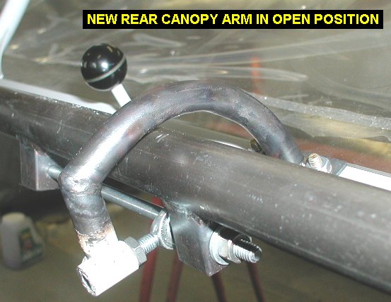
| 03/01/03 |
6.6 |
588.7 |
Welded the top fairing angles on the top
longerons, that took about an hour and a half. Welding on the longerons
must have moved them a little, because it made the canopy work even
better, what a nice surprise it now latches with one finger. Then I spent
5 hours (until 2am) on the canopy hinge arms. First I had to figured out
which was front and back, it took some test fitting since neither of them
lined up exactly with the long 1/4" slider bolt. I worked on the
front one and was able to bend it so it would line up and slide ok. The
rear one though was at least 3/8" off, too far to bend in my opinion
especially since the front one distorted a little after bending. I decided
to cut the mitered joint loose, shorten the little horizontal tube out and
re-weld it. After tack welding, it worked great and the canopy slid ok,
but when I opened the canopy up....the arm hit the longeron as it rotated
up...Dangit! So I took out my torch and reworked it a bit and got it
working, but it was so ugly with all the changed bends that I decided to
make a new curved tube. I cut the old tube away from the angle bracket
that attaches to the canopy, bent a new one (1/2 x .035 tube) into a nice
curve a torch, and tack welded it. After it tested ok, opening up with
plenty of clearance over the longeron, I welded it up. I now have a lot
more appreciation for all the work Kevin has in designing this canopy
system, it works great! |
 |
 |
 |
 |
| 03/02/03 |
2.0 |
590.7 |
Worked on front w/s sheetmetal, adjusting
the fit. Also took a little more off the aft left edge of the w/s itself,
for a more even gap between it and the canopy. |
| 03/03/03 |
3.3 |
594.0 |
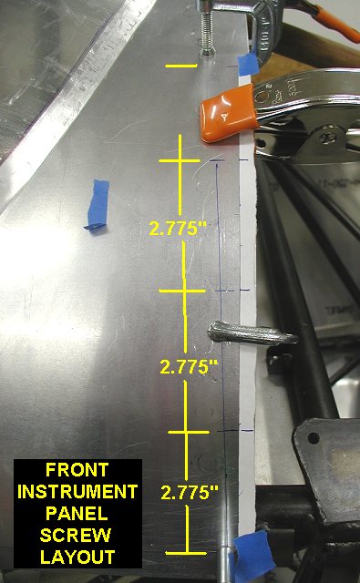
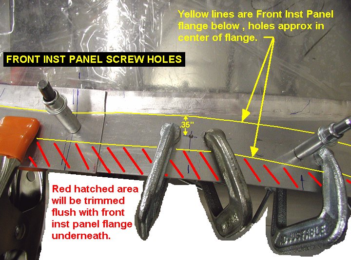
Did some layout for screwlines on the w/s
corner panels. I used the depth gage of my calipers to figure out where to
drill to place each hole in the middle of the instrument panel flange,
basically depth from edge-.35" equals distance from edge to drill. I
measured the overall length of the screwline and spaced them equally by
using marks on tape. I then drilled and put clecos in the top center of the front
instrument panel where the w/s corner panels overlap. Note that when I
drilled I had 2 clamps on either side of the hole, this keeps the gap
between sheets getting filled with chips and messing up a tight cleco
joint. Also put 2 clecos
each side in the bottom edges of the panels and top longeron fairing
angles. Then added clecos on the rest of the front instrument panel
upper edge. |
 |
 |
 |
| 03/04/03 |
2.1 |
596.1 |
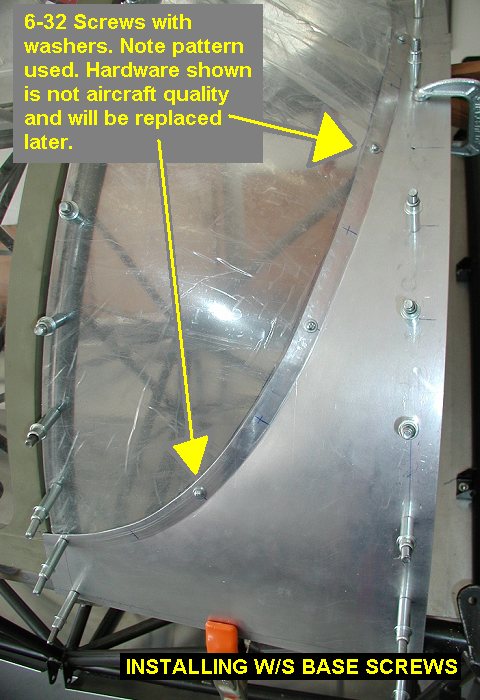
Finished layout of screwlines
for the w/s base edge. I drilled through the aluminum and plastic with
#40, 7/64 then 9/64 to get a nice hole for 6-32 screws and nuts with
washers. I also drilled and installed screws in an even pattern skipping
around to spread any clamping forces around, as opposed to working from on
end to another. Note that hardware shown in pictures is not final aircraft
hardware I'll use, I just can't wait for UPS to come everytime I need to
get work done. |
 |
 |
 |
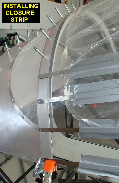
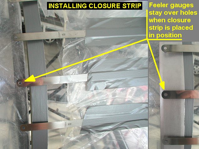
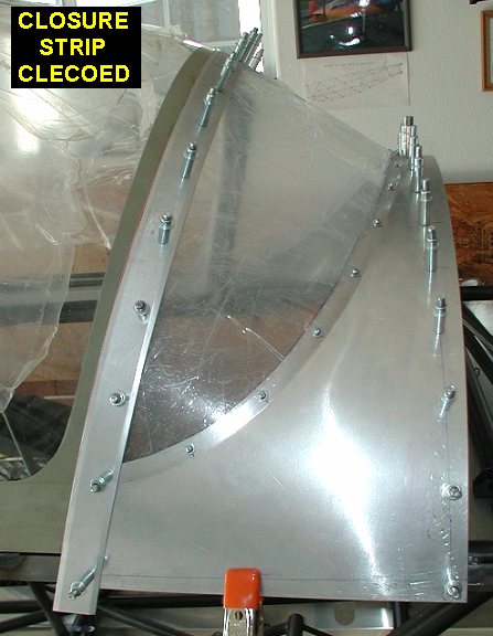
| 03/05/03 |
1.7 |
597.8 |
Installed canopy / windshield
closure strip. I found my set of long feeler gauges were pretty handy for
marking where to drill the strip so the holes would line up. The two
strips were labeled top, but I had to figure out which was left and right.
They have a 3/4" overlap at the top and the left one was installed
first, just like the w/s base panels. I also had a couple of layers of
duct tape temporarily on the canopy edge to make sure I didn't get the
strips too tight on the canopy. |
 |
 |
 |
| 03/08/03 |
1.2 |
598.8 |
Marked the w/s corner panels and trimmed the
forward edge of them flush with the front edge of the fwd instrument panel
flange. It took awhile because I had to disassemble the w/s from the
corner panels to cut with the snips and debur them. |
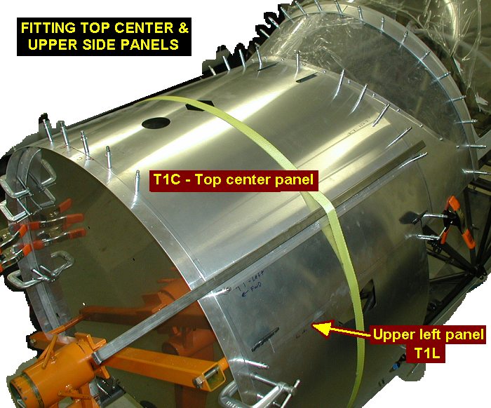
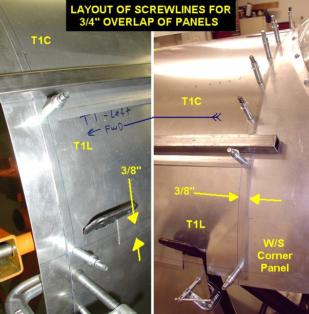
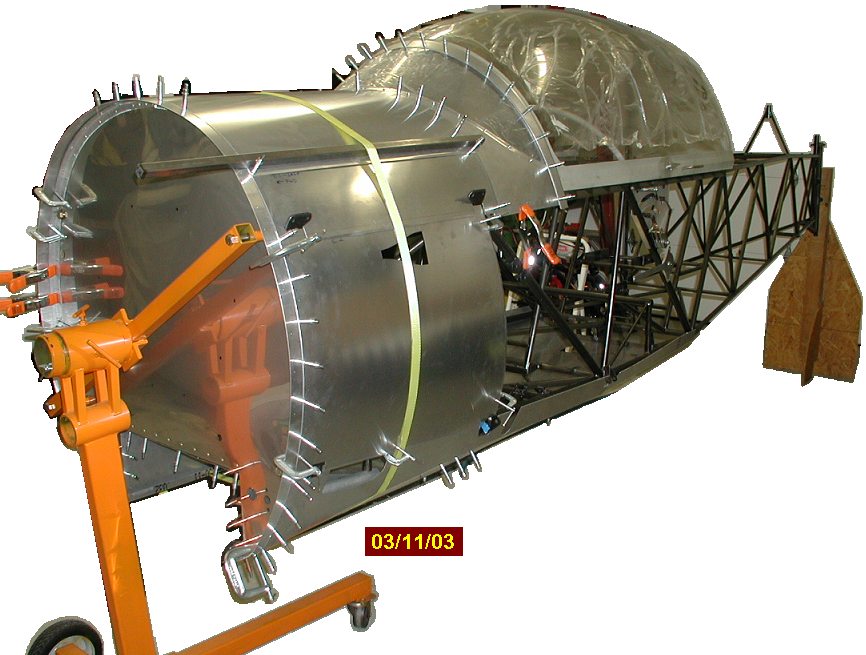
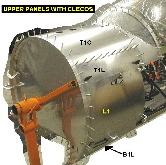
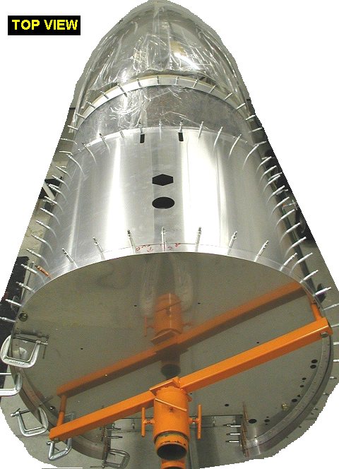
| 03/11/03 |
3.5 |
602.3 |
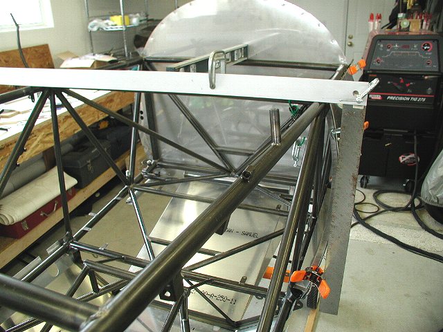
Marked the centerline of the top
center panel T1C (has cutouts for fuel cap and sight gauge) and then
positioned to cowl ring in front and windshield panel with clecos on c/l
at each end. Using my dremel with flex shaft
attachment to drill #40 holes in T1C through the existing holes in the
cowl ring and front instrument panel, I clecoed my way from center out to
the edges. I then set the T1L and T1R upper side panels into position
getting them even with T1C and then drew lines on all the panels for the
screwlines. The strap and square tubing act to keep the lower edge of T1C
flat without bowing up. Basically the lines go 3/8" from the edge of
the panels, which makes them overlap by 3/4". I drilled and clecoed
the corners of T1L and T1R. |
 |
 |
 |
| 03/12/03 |
1.6 |
603.9 |
Removed the top panels, then drilled and
clecoed the 3 T1 panels together. Took them apart, then put them on the
fuselage, and drilled & clecoed the rest of the holes in the T1 L
& R panels, except for the top longeron strips. I'll wait and do them
when I have the L1 and R1 panels up in position. |
 |
 |
| 03/25/03 |
3.5 |
607.4 |
Did the layout work, drilled and clecoed the
rest of panels L1, B1L & R1. All work done a little here and there
since march 12, I had my airline proficiency check 15th-17th then sinus
surgery on the 21st. |
 |
 |
| 03/26/03 |
1.5 |
608.9 |
Located drilled and clecoed panel B1R into
position. Now have all forward sheetmetal fitted and ready for screws and
nutplates. |
 |
| QTR TOTAL |
76.4 |
|
|
|
|
|
|
1ST QTR 2003
|
•
•
•
|


