|
1ST QTR 2004
|
 •
•
 •
•
 •
•

|
| DATE |
HRS |
TTD |
ACTION |
IMAGES |
| 01/14/04 |
2.5 |
699.5 |
Took everything off the fuselage
except canopy and front windshield so I can start welding more stuff on
the frame. |
| 01/15/04 |
1.3 |
700.8 |
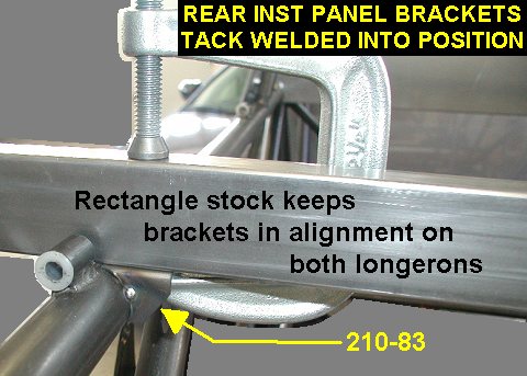
Tack welded the rear instrument
panel tabs onto the longerons at FS 59.3 (6.3 aft of the crossmember) |
 |
| 01/20/04 |
4.3 |
705.1 |
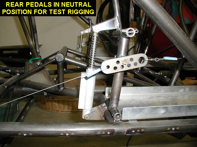
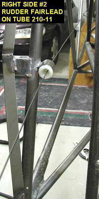
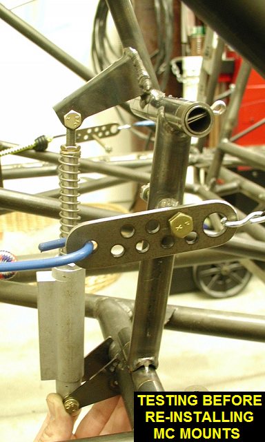
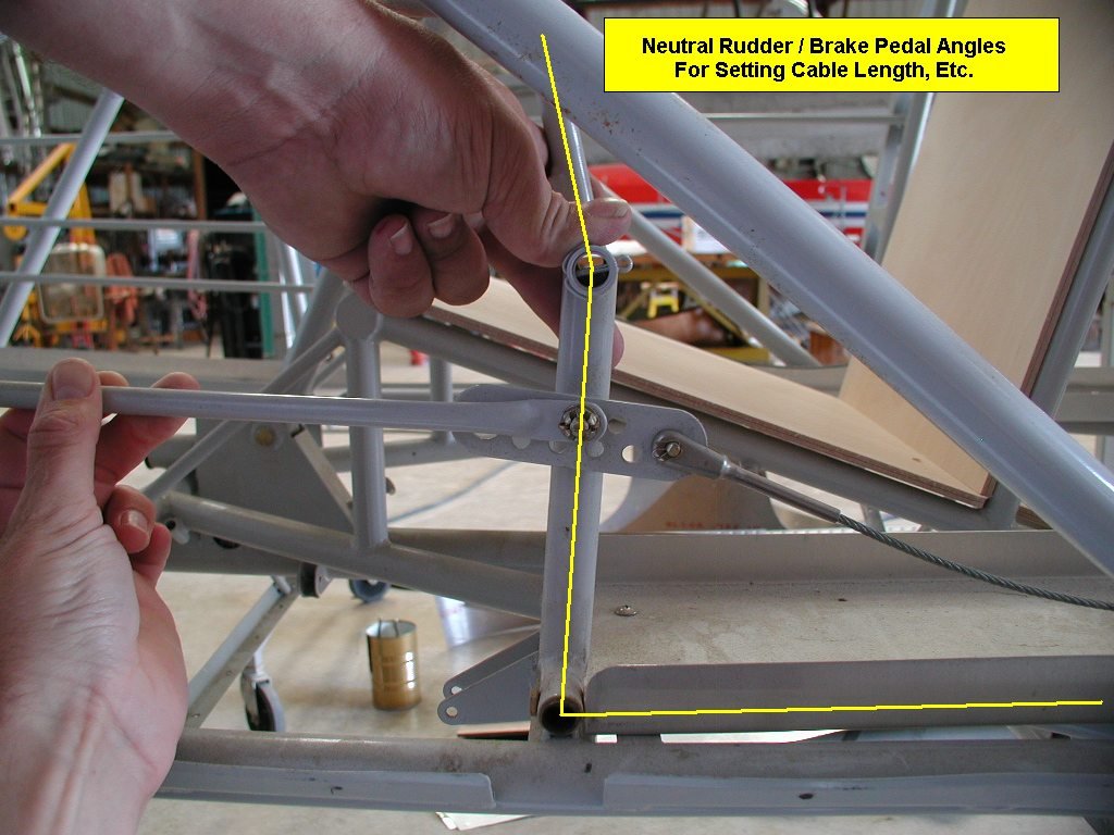
Removed canopy.
Installed rear seat rudder pedals, and did some more work with the
adjustable reamer to get the hinge pins sliding in/out nice and smooth.
Using This Picture
as an initial guide I used some bailing wire to set the rudder and brake pedals in
a neutral position. After comparing mine to the picture, I just realized
that I need to rotate my master cylinder lower mounts downward a little to
get them set up better. I'll do it later, good thing they are only tacked
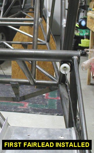
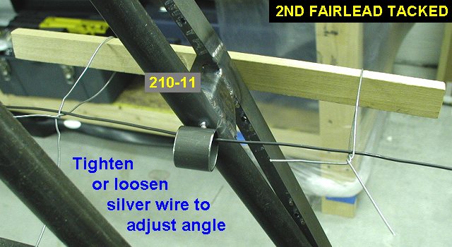
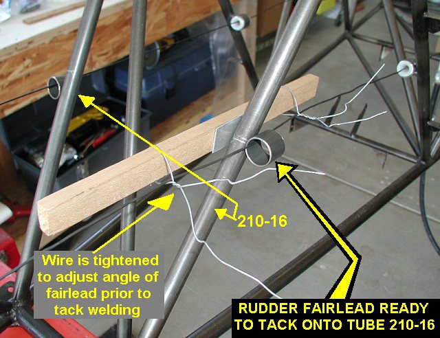
at this point. I then strung some more bailing wire to simulate the rudder
cable and proceeded to weld on the first 4 fairlead tubes. I used a short
length of wood and more wire to pull the fairlead tube tight against the
fuselage tube and adjust its angle. I eyeballed the angles of the
fairleads to split the difference between the fairlead stations. I'm not
sure how many I'll need yet, but I've got 22 fairlead tubes cut ( 7/8 Dia.
x .049 Wall x 3/4" Long 4130 tube) which then use Aircraft Spruce P/N
05-05600 3/4" X 1" Fairlead Assemblies. |
 |
 |
 |
 |
| 01/21/04 |
2.0 |
707.1 |
Welded the aft 4 rudder cable
fairleads onto fuselage. |
 |
| 01/27/04 |
3.3 |
710.4 |
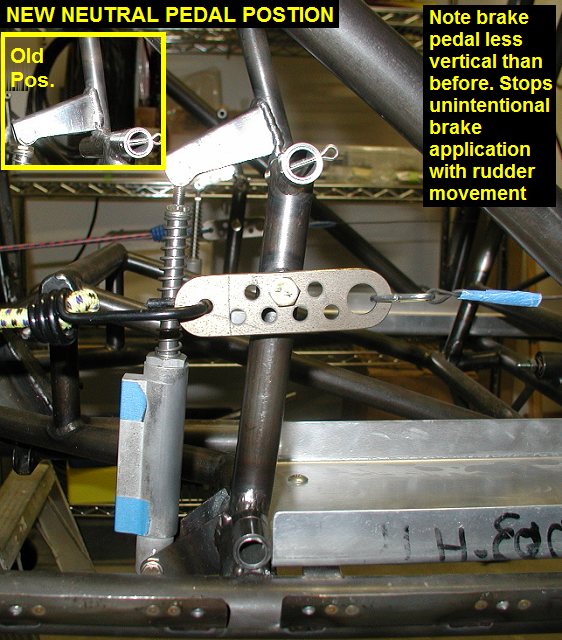
Adjusted wire to
equal pedals at neutral position. With my master cylinders (MC) in the
middle of their adjustability range, I discovered that the lower MC mounts
were too high because at rest, my feet were pushing on the brake pedals
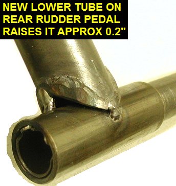
instead of the rudder pedals. Tested Phil's taller pedals and found them
too tall for my shoe size. I decided to raise my rear pedals just a little
and also lower the MC mounts to look more like the Kimball fuselages. To
make my pedals a little taller I cut most of the bottom hinge tube off one
of the pedals and fit a new hinge tube on, raising the pedal about 0.2
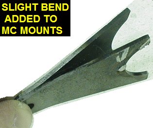
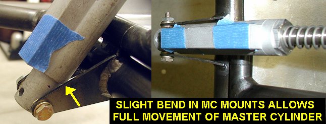
inch. I also cut the tack welds and removed the lower MC mounts, then put
a slight bend in them to allow full aft MC rotation in the mount without
interference. |
 |
 |
| 01/28/04 |
3.5 |
713.9 |
Finished cutting and
fitting other pedal, then tack welded them. Installed pedals and tested
various lower MC mount angles, various MC lengths by adjusting the top eye
bolt in/out of the MC. I also tested various settings of the 510-30
adjuster plate before settling on a lower MC mount position. I then welded
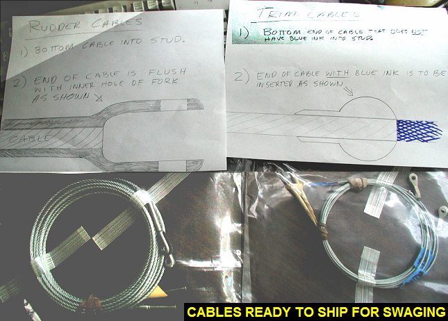
the pedals and and MC mounts in position. I also ordered the cables and
other related hardware for fitting. I plan on sending them to Kevin for
swaging. On my last layover, and based on measurements of a Kimball fuse,
I made up a drawing of the Cables
& Fairleads. |
 |
 |
 |
 |
| 02/04/04 |
3.0 |
716.5 |
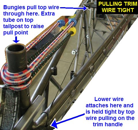
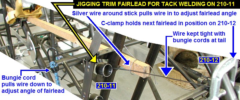
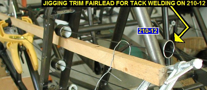
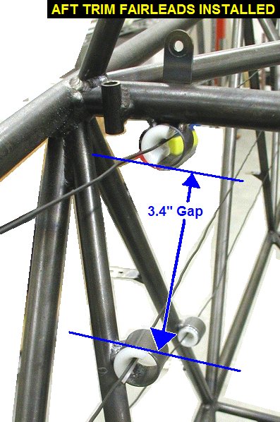
Installed stabilizer
and trim handle. Ran bailing wire in preparation of installing trim
fairleads. Discovered that I could pull wires from just above the tail
post and upper right longeron to locate the fairleads, thus allowing me to
remove the stab for better access. Installed and welded up the trim
fairleads as per Cables
& Fairleads. |
 |
 |
 |
 |
| 02/09/04 |
1.0 |
717.5 |
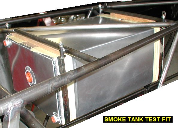
Since I'm waiting for parts to
arrive so I can work on the cables, I decided to work on mounting some
tanks. I sorted out the 3/4" x .030 SS bands that came with the tanks
and rounded / deburred the ends. I also marked the midpoints with a felt
tip. |
| 02/10/04 |
1.0 |
718.5 |
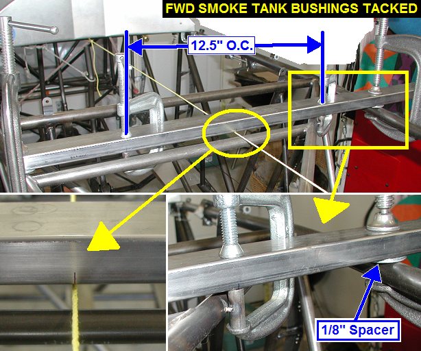
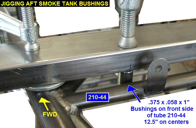
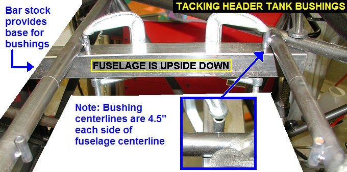
Figured out a way to jig up the
210-79 bushings for the smoke tank. See Smoke
Tank Bushings Drawing. I clamped them flush with the edge of some
rectangle tube and 12.5" on centers. Then I set the tube on the
longerons with 1/8 thick spacers and aligned the bushing center with
fuselage centerline before tack welding them on. Most of the bushing hangs
below the tube so that the mount bolts go up thru the turtle deck floor to
make installation/removal easier. |
 |
 |
| 02/12/04 |
1.7 |
720.2 |
Welded the smoke tank bushings. |
 |
| 02/18/04 |
1.2 |
721.4 |
Finally got all the needed
hardware for the cables, so I installed the rudder and pedals. I then
determined the rudder cable length I needed and cut it to length. Removed
rudder and fin. Sorry forgot to take pictures, you can see it all later
when I get the cables back from Kimball's with the ends swaged on. |
| 02/19/04 |
1.7 |
720.2 |
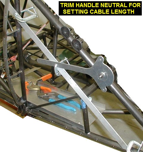
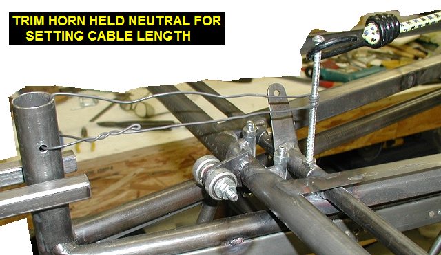
Installed stab and used various
methods to lock the trim handle and trim horn in position to determine
cable length See Trim Horn
Diagram. I then cut the trim cables down a bit and left a little extra
to extend beyond the ball at the end. I then packed up all the cables and
swage ends and FEDEXed them to Kevin Kimball for swaging. |
 |
 |
 |
| 02/25/04 |
1.8 |
722.0 |
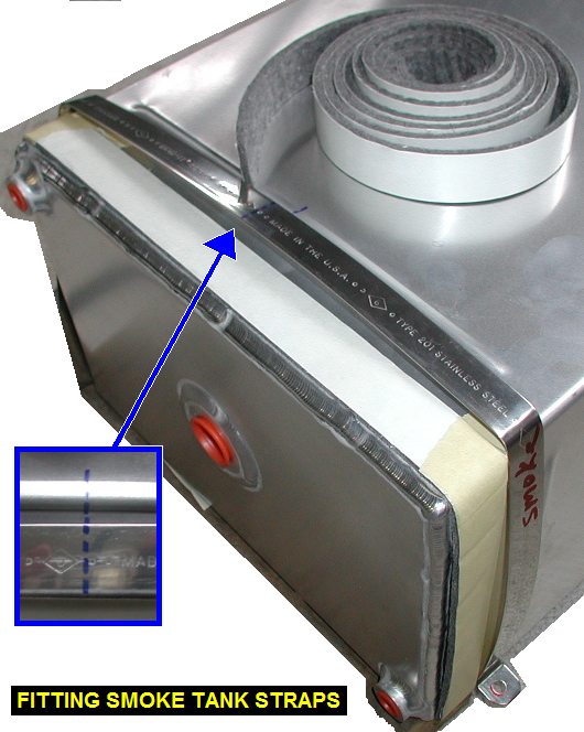
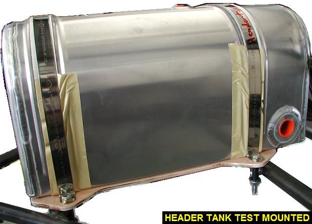
Back to the smoke tank, I cut
and taped some of the 1" felt to go around all but the top side of
the tank. I didn't use the adhesive yet since I haven't painted the tank
yet. I then bent the 90 deg bends for the bolts into the SS strap and then
the two bends for the corners of the tank, keeping the center marks of the
strap aligned with the center of the tank. l found some 1/2x3/4 scrap wood
to use as a test spacer for the smoke tank, and did a test mount which was
ok. Ripped some 1/2x3/4 poplar stock to use for the real spacers which
will have a 3" gap in the middle for the aft shoulder harness to
pass. |
 |
 |
| 02/26/04 |
4.0 |
726.0 |
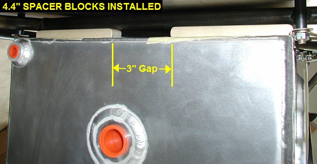
Installed the turtledeck and
drilled 1/4" holes up through the smoke tank bushings into the floor
of it. Cut four of the wood spacers (4.4" each) and did some test
fitting of the tank. Ended up sanding the wood down to .450 thick to get a
good snug fit of the tank with the bolts pulling the straps up tight
against the bushings. Moved on to the header tank, see Header
Tank Bushings Drawing. Marked the centers of the two straps for it.
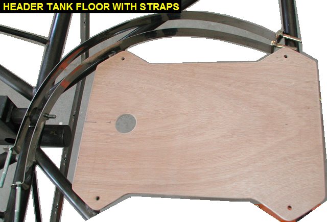
Cut oversize a piece of 1/4 birch plywood to use for a tank floor, I'll
trim it down to size after I get the holes drilled in it later. Located,
tacked then finish welded the header tank bushings in. Note the top end of
the bushings are flush with the tops of the tubes so the floor lies flat. |
 |
 |
| 02/27/04 |
0.6 |
726.6 |
Located and drilled the
1/4" holes in the plywood tank floor. Also located and cut the 1.25
dia. hole in the tank floor for the tank drain. |
 |
| 03/02/04 |
1.5 |
728.1 |
Taped the felt material around
the tank and bent the 90° angles in the straps. Test fitted the tank and
marked where to trim the tank floor board further. Cut the floor board to
shape and sanded edges. |
 |
 |
| 03/04/04 |
0.6 |
728.7 |
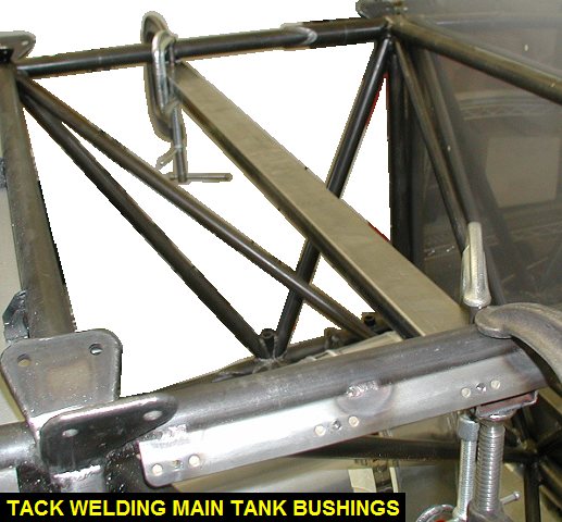
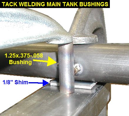
Started work on main tank mount
bushings, see Main Tank Bushings Drawing.
Measured and marked their locations. Jigged and tack welded the aft
bushings. I used a 1/8" shim between the rectangle stock and the
longeron, this put the 1 1/4" long bushing center on the 1"
diameter longeron. |
 |
 |
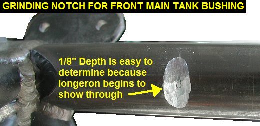
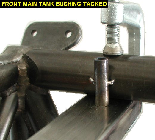
| 03/08/04 |
1.8 |
730.5 |
Used cutoff wheel to cut notches
in the upper engine mount sleeve for the forward main tank bushings. It
was easy to determine how deep to go, as I just went until the 1"
longeron inside started to show through. Jigged up and tack welded the
bushings in. Cut a tack weld loose on the crooked aft one (see
picture from 3/4/04) and straightened it out with another tack weld. |
 |
 |
| 03/10/04 |
1.3 |
731.8 |
Welded up the main tank
bushings. |
 |
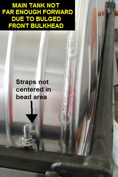
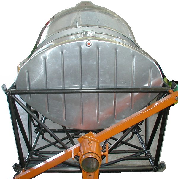
| 03/13/04 |
0.8 |
732.6 |
Installed bottom straps and test
fit tank. The tank didn't go far enough forward due to bulged front of
tank, evidently from pressure test. To fix it I set it on some carpet and
used a 2x4 to hold the front down while pushing down around the
circumference of the tank front until the bulge was gone, and it actually
popped inward a little. I'm sure this inward bulge will disappear as soon
as the tank gets filled for the first time. I'll add some felt to the
crossmember for the tank to push against later when I install the tank. |
 |
 |
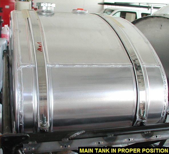
| 03/15/04 |
2.0 |
734.6 |
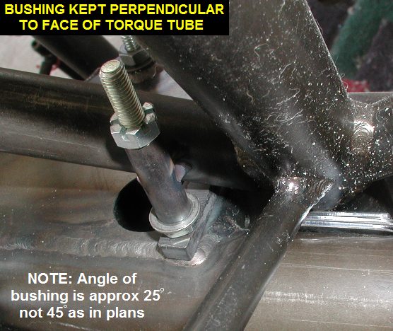
Temporarily taped
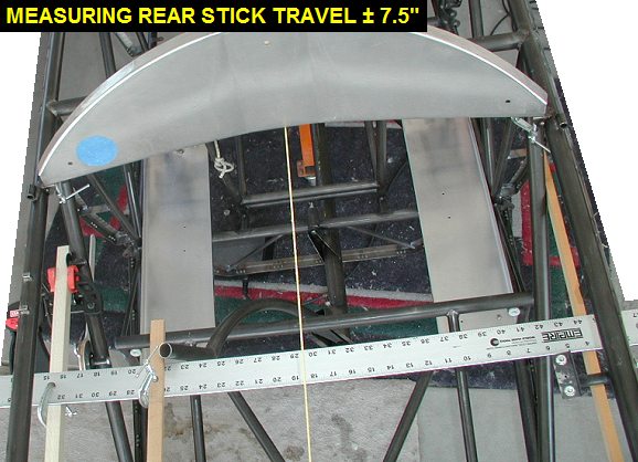
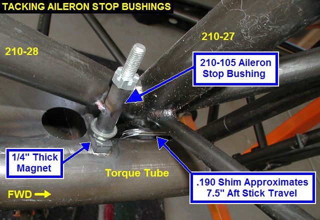
the felt around main tank to test fit the straps. Next I began work on
locating the aileron stop bushings 210-105 by putting a .190 shim between
the torque tube and the crossmember there, and using a magnet to hold the
bushing with a bolt perpendicular to the front stick tower. Kevin said to
set up the stops to get at least ±7.5 inches travel left/right (total 15)
at rear stick top. Of course final rigging is done by setting AILERON
TRAVEL not stick travel, this method only ensures enough travel is
available. I then tack welded the bushings in. NOTE: The bushings get
welded in at approx 25° instead of the 45° shown in the plans. I
wish I had done this BEFORE putting in the 210-66 belly former support
tubes at FS 24.9, the welding will be more difficult now! |
 |
 |
 |
 |
| 03/17/04 |
1.6 |
736.2 |
Welded up the Aileron stop
bushings. Note the reduced 25° angle in the picture. |
 |
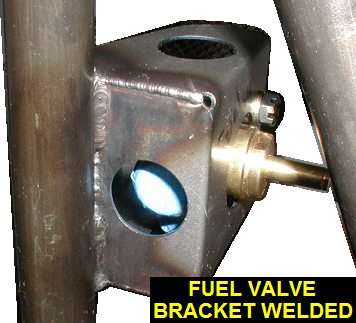
| 03/18/04 |
0.5 |
736.7 |
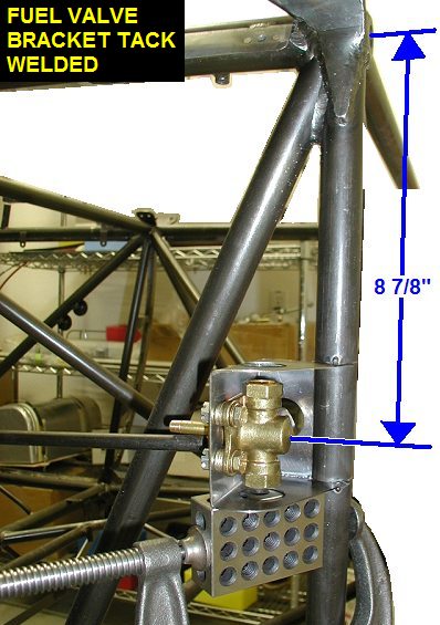
Welded up the edges of the fuel
valve bracket. |
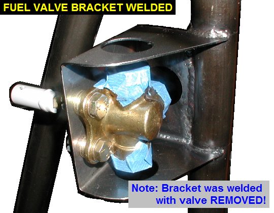
| 03/19/04 |
0.5 |
737.2 |
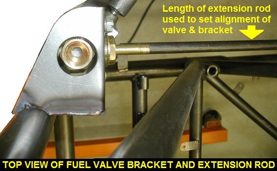
Bolted the fuel valve into the
bracket for test fitting. Jigged it into position so that the center of
the bracket was 8 7/8" below the center of the top right engine mount
bolt, which is slightly different from plans, but same as Kimball HP. Also
I used a long tube to simulate the fuel selector extension rod so I could
set the valve at the proper alignment. Used a clamp and 123 block to hold
the bracket for tack welding. |
 |
 |
| 03/25/04 |
2.0 |
739.2 |
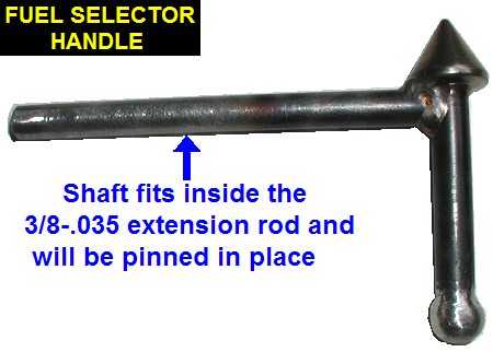
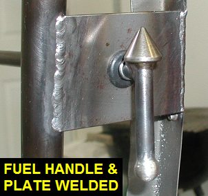
Made a fuel selector handle by welding a
stainless cap nut on a tube and turning it down to a point on a lathe. I
then welded a steel ball on the other end. |
 |
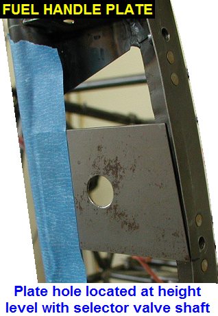
| 03/31/04 |
1.6 |
740.8 |
Tack welded the fuel handle plate onto
tube 210-9 and the side former there. Finish welded the plate and the fuel
valve bracket. |
 |
 |
 |
 |
| QTR TOTAL |
43.8 |
|
|
1ST QTR 2004
|
•
•
•
|


