|
4TH QTR 2003
|
 •
•
 •
•
 •
•

|
| DATE |
HRS |
TTD |
ACTION |
IMAGES |
| 10/02/03 |
3.2 |
683.7 |
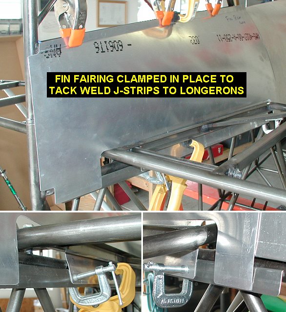
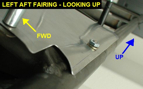
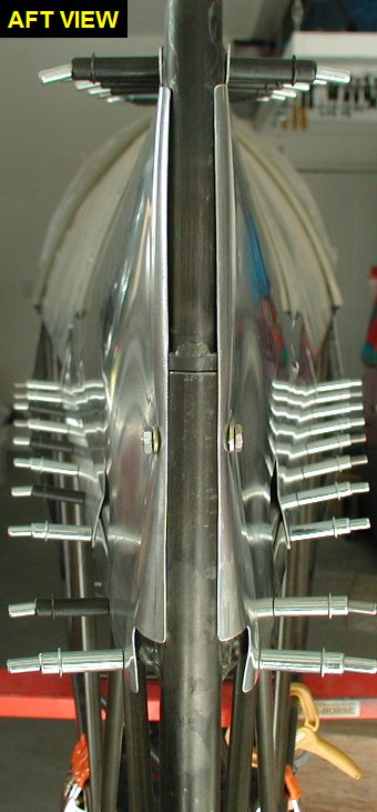
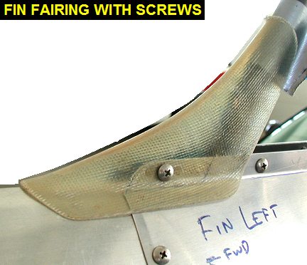
Clamped the fin
fairings in position, located the J-strips onto the upper longerons and
tack welded them on. Removed fairings and did the skip welds. Located and
drilled holes to match the nutserts around the aft bulkhead of the
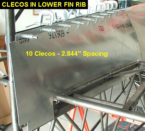
turtledeck. Located, drilled #40 and clecoed holes in bottom fin rib and
J-strips to hold fairing in place. The fin rib has 10 clecos spaced
2.844" apart. The longeron J-strip has 2 clecos at the rear 2.5"
apart then 8 clecos forward of that 3.14" apart. Removed fairings and
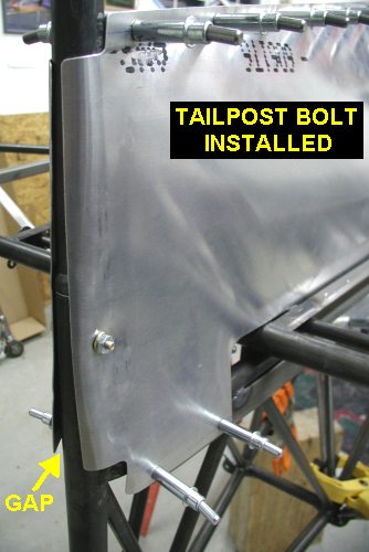
drilled 3/16 hole 1" down on tailpost thru fin aft spar for AN3-13A
bolt. Reinstalled fairings one at a time to back drill 3/16" thru
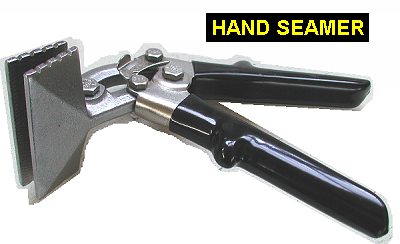
tailpost and fairings. Did some initial forming of the aft vertical edges
to the tailpost with a hand seamer. |
 |
 |
 |
 |
| 10/16/03 |
2.1 |
685.8 |
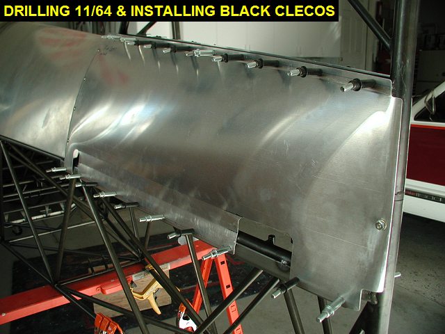
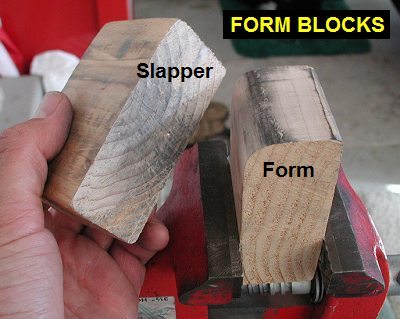
Improved fit of the
fin fairings. Used 2x4 form blocks to rework the curves at the tailpost.
Trimmed the aft edges of the fairings to fit good with the rubber gap
seals I'll be using. Removed stab and then drilled out the #40 cleco holes
to 11/64 in prep for installing nutplates. |
 |
 |
 |
 |
| 10/20/03 |
2.5 |
688.3 |
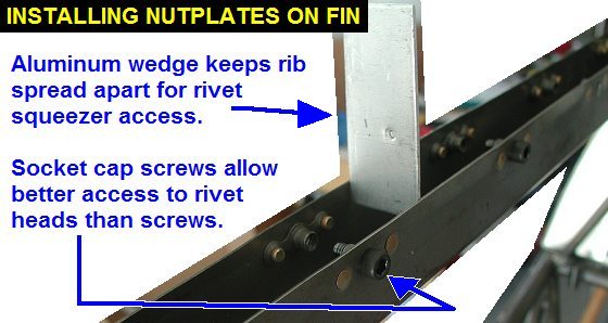
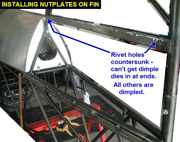
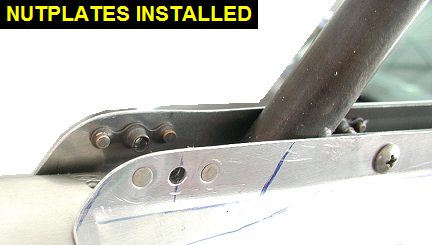
Installed nutplates in fin and
fuselage J-strip for fin fairings. |
 |
 |
| 10/30/03 |
2.0 |
670.3 |
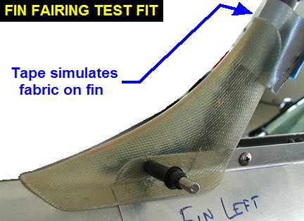
Test fit fairings. Did a little
more adjustment to the left fin fairing aft edge curve so it wrapped
around the tailpost better. Removed fairings and trimmed upper front
corners to fit better with fiberglass trutledeck to fin fairing. Drilled
holes and installed nutplates in fin fairings to hold it. |
 |
 |
 |
| 11/01/03 |
2.4 |
672.7 |
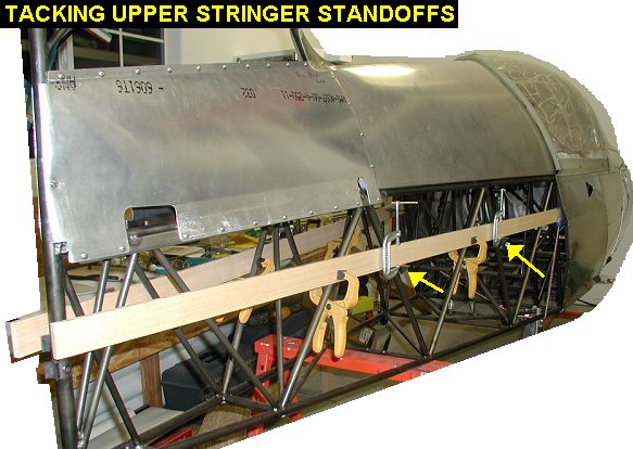
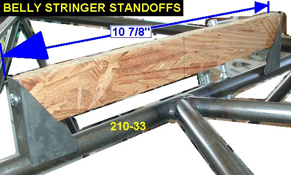
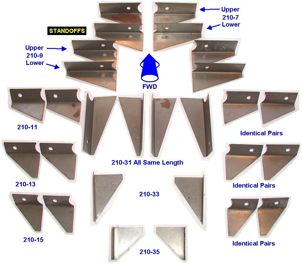
Located and tack welded the
stringer standoffs onto vertical tubes 210-13 and 210-15 using a length of
stringer material on edge and clamped to the other vertical tubes for
support. For a picture of the standoffs sorted click
here. Note that the standoffs that weld onto tube 210-13 stick out
more than the ones for 210-15 because the stringers taper as they go aft.
See Tail Stringer Drawing for
details. |
 |
 |
 |
| 11/02/03 |
1.0 |
673.7 |
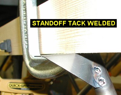
Finish welded the stringer
standoffs. |
| 11/10/03 |
1.0 |
674.7 |
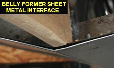
Fitted the ends of the side
stringers into the formers at Tube 210-11. I ended up putting a
"step" in the stringers so the stringer fits tight in the
former, but also so the exposed part of the stringer is flush with the
edge of the steel former. This is done to ensure a smooth fabric
transition at each stringer. |
 |
| 11/19/03 |
1.5 |
676.2 |
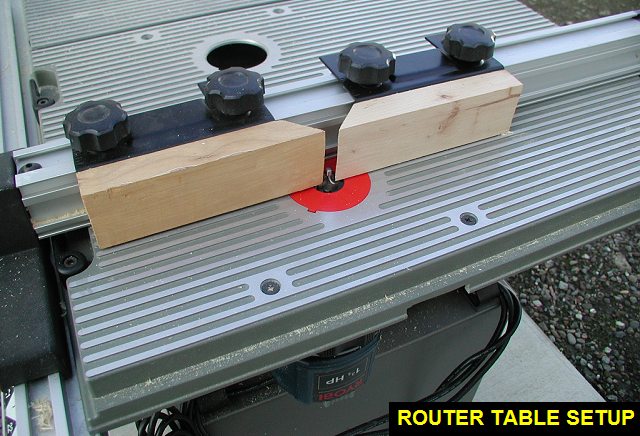
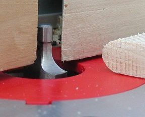
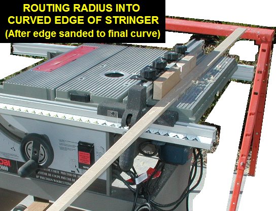
Bought a 1/4" radius router
bit, and set up my router table on my table saw. Did some testing on scrap
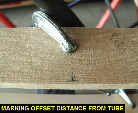
stringer material to get the radius cut right. Using offset measurements
taken on a recent visit to Kimball Enterprises, I did some layout on the
3/8" x 1 3/4" spruce stringer stock. |
 |
 |
 |
| 11/26/03 |
2.8 |
679.0 |
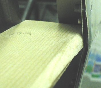
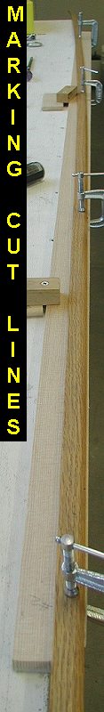
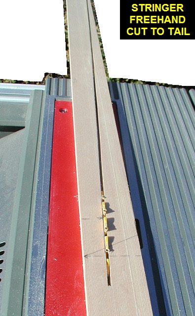
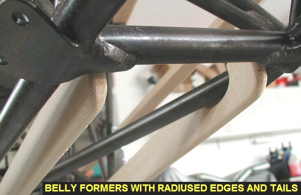
Finished layout on the side
stringers using a strip of oak trim clamped in a curve fitting to the
offset marks drawn earlier. I then cut the stringers freehand on the table
saw, note that I left the stringers extra long so I would have plenty of
wood to hold onto as I neared the end of the cut. I then used a sanding
block to fine tune the curved edges and finally routed the radiuses into
the curved edge. |
 |
 |
 |
| 12/01/03 |
1.0 |
680.0 |
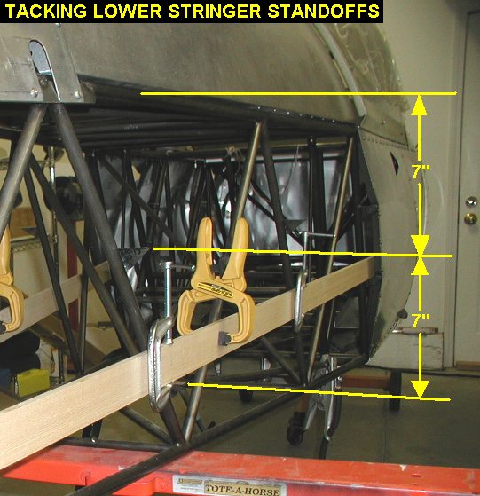
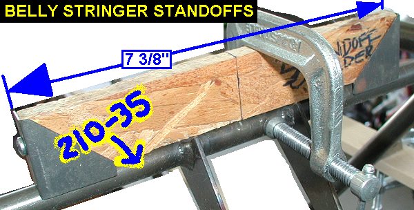
Made a couple of simple wood
jigs to hold the belly stringer formers on tubes 210-33 and 210-35. Note
that Kevin omits the standoffs at tube 210-37. Also the standoffs at
210-33 are 10.875 apart, and the ones at tube 210-35 are 7.375 apart. This
is different than plans. |
 |
 |
| 12/02/03 |
3.3 |
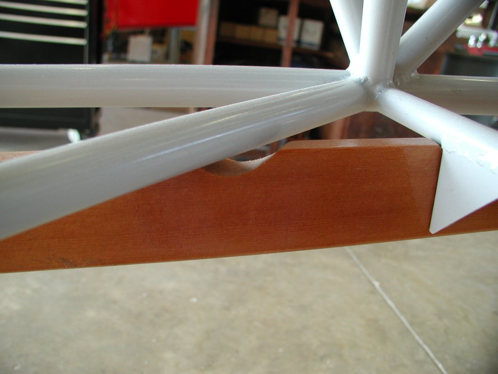
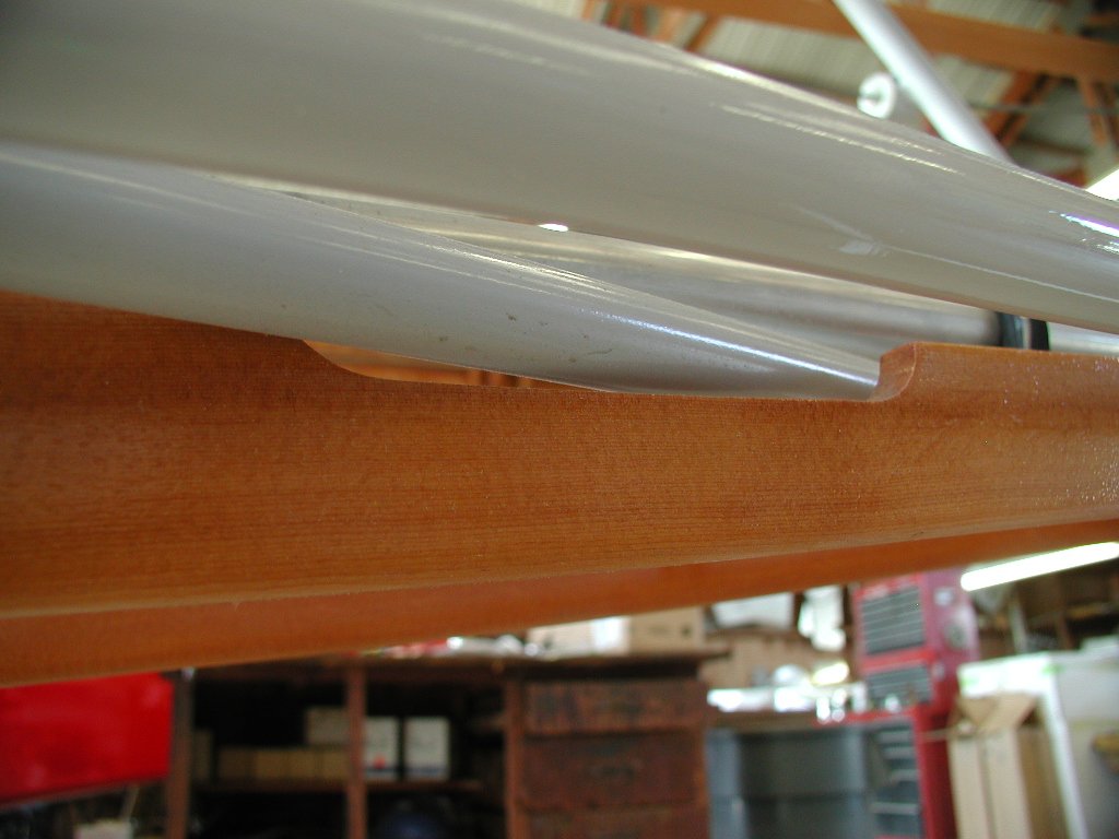
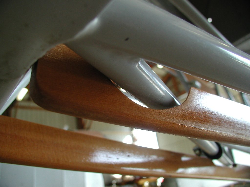
683.3 |
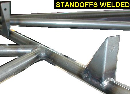
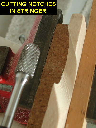
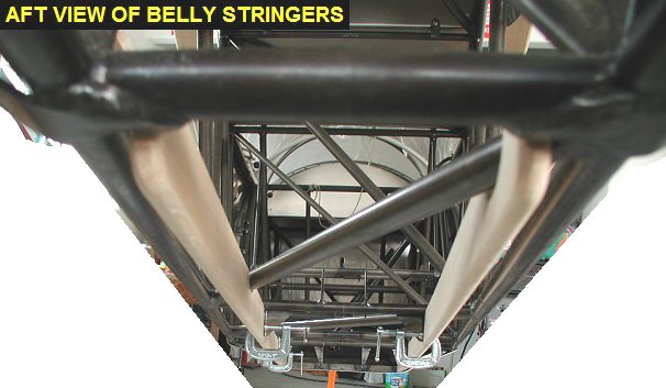
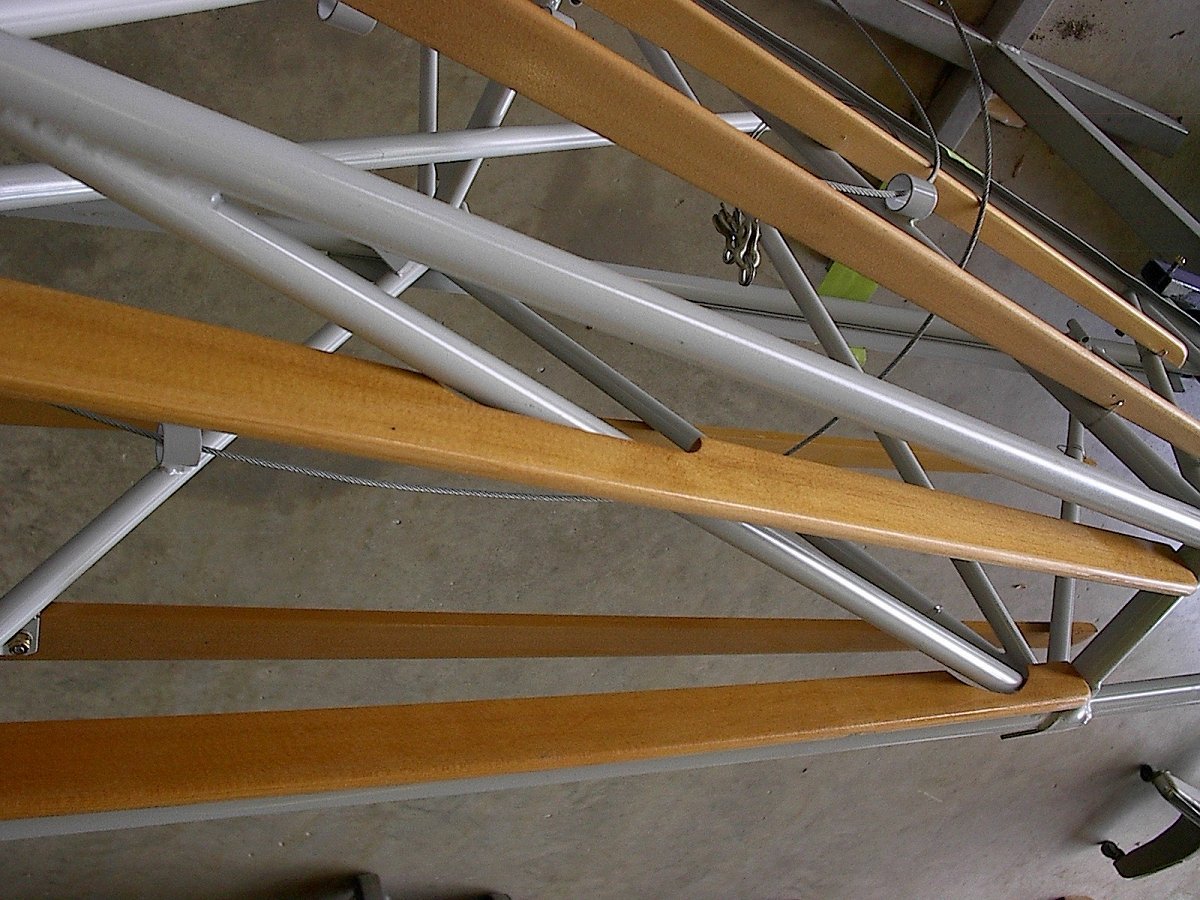
Welded the standoffs on tubes
210-33 & -35.Cut the two bottom stringers to length then began fitting
the upper edges of them to fit up into the fuselage structure as shown in
pictures Stringer
Detail, PB147586,
PB147589, and PB147590.
I used a die grinder to cut the notches in the stringers a little bit at a
time until the fit similar to the example pictures. |
 |
 |
| 12/03/03 |
0.8 |
684.1 |
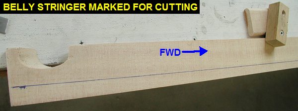
Marked and cut the lower edge of
the belly stringers but didn't have time to cut the radiuses. |
 |
| 12/04/03 |
2.2 |
686.3 |
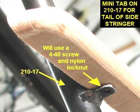
Did some more
fitting of the bottom stringers, mostly to the diagonal tubes but also the
front where they meet the sheetmetal. Used a long sanding block to smooth
the bottom curves cut the day before, then I touted the radiuses. I didn't
like how the side stringers flopped around at the tails without support
from tube 210-17, so I used some left over 4130 sheet from my laser cut
fittings to make some miniature tabs to weld onto the tubes. Basically I
cut a narrow strip of the sheet drilled a small hole (for a 4-40 model
airplane screw and locknut) near one end and then welded it in the proper
position on tube -17. Afterwards, I used a dremel cutoff wheel to trim the
tab to length and free up the strip to make the next tab. Leaving the tab
long while welding kept it from overheating and melting away during the
tedious welding. I got 2 of the 4 aft "mini" tabs installed. |
 |
 |
 |
 |
| 12/06/03 |
1.0 |
687.3 |
Welded on the other 2 mini tabs,
then drilled holes on the side and belly stringers for mounting to the
standoffs and mini tabs. |
| 12/16/03 |
1.5 |
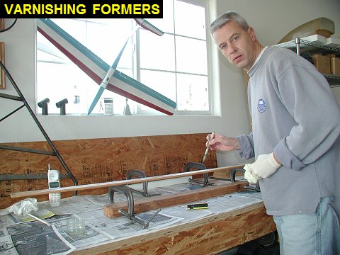
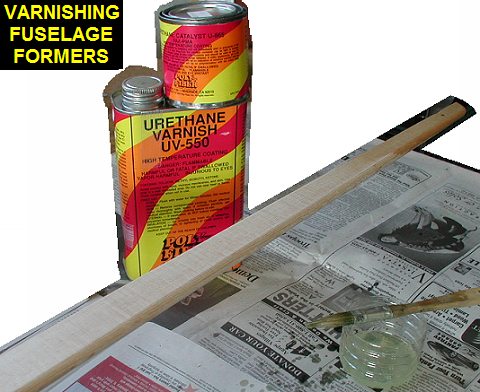
688.8 |
Put on first coat of Polyfiber
UV-550 urethane varnish on the fuselage side and belly formers. The UV-550
is mixed 2:1 with the U-865 catalyst. |
 |
 |
| 12/22/03 |
1.3 |
690.1 |
Put the second coat on the stringers. |
| 12/29/03 |
2.4 |
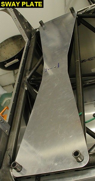
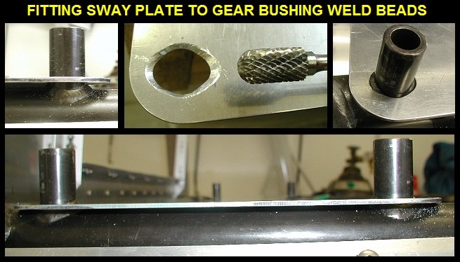
692.5 |
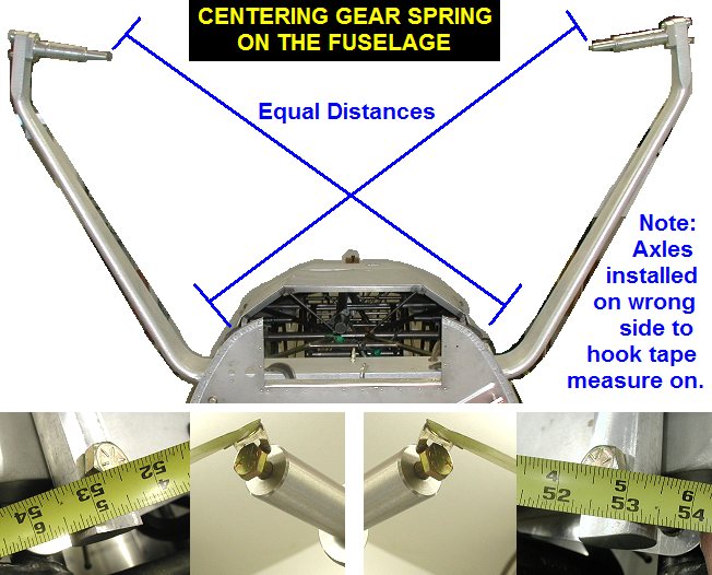
Switched efforts to the landing gear, by
fitting the sway plate to the fuselage. Because of the weld beads around
the landing gear bushings, I used a die grinder to take material away from
around the holes so the plate would sit flat against the longeron. Next I
set the landing gear spring in place (that spring is heavy for one
person!) and installed the axles backwards so I could take some
measurements to center it on the fuselage. I then clamped the sway plate
to the spring such that the two would stay together when the spring was
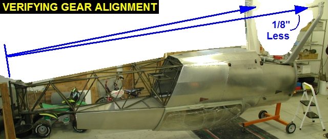
removed for drilling. Also I took some measurements from the tail to each
gear leg to verify the alignment, the left leg is 1/8" aft of the right. |
 |
 |
 |
 |
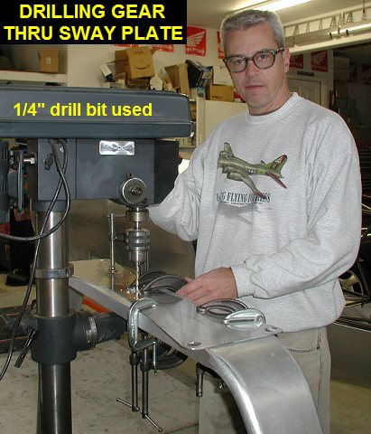
| 12/30/03 |
4.5 |
697.0 |
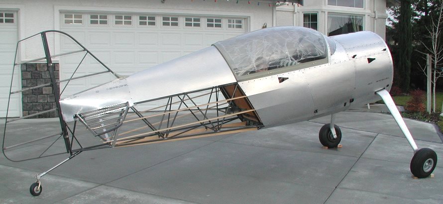
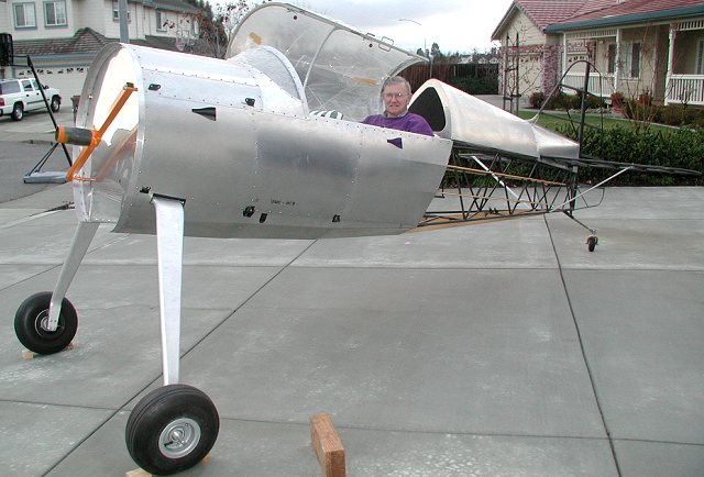
My dad came over and helped me take the
spring off and drill the 1/4" hole through the gear spring. Since I
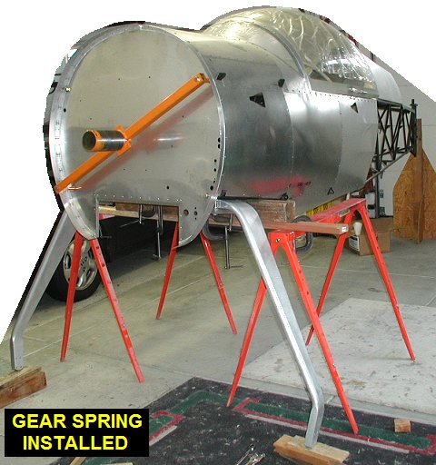
had used several clamps to hold the sway plate on the gear it was easy to
locate and drill on the press. We then lifted the fuselage up on saw horses and installed the sway plat
and gear spring. Next we temporarily installed the axles and wheels and tires. Note
the wheel halves got torqued to 130 in-lbs after installing the tubes
& tires. We then put the bottom
sheetmetal, tail feathers, tailwheel and stringers on and rolled it out in
the driveway for some pictures. |
 |
 |
 |
 |
| QTR TOTAL |
16.6 |
|
|
4TH QTR 2003
|
•
•
•
|


