|
1ST QTR 2009
|
 •
•
 •
•
 •
•

|
| DATE |
HRS |
TTD |
ACTION |
IMAGES |
| 01/07/09 |
0.5 |
1000.7 |
Used an adjustable reamer to
remove powdercoating from inside the engine mount bushings. Before that I
couldn't get the 1/2 bolts through them. |
 |
| 01/15/09 |
2.0 |
1002.7 |
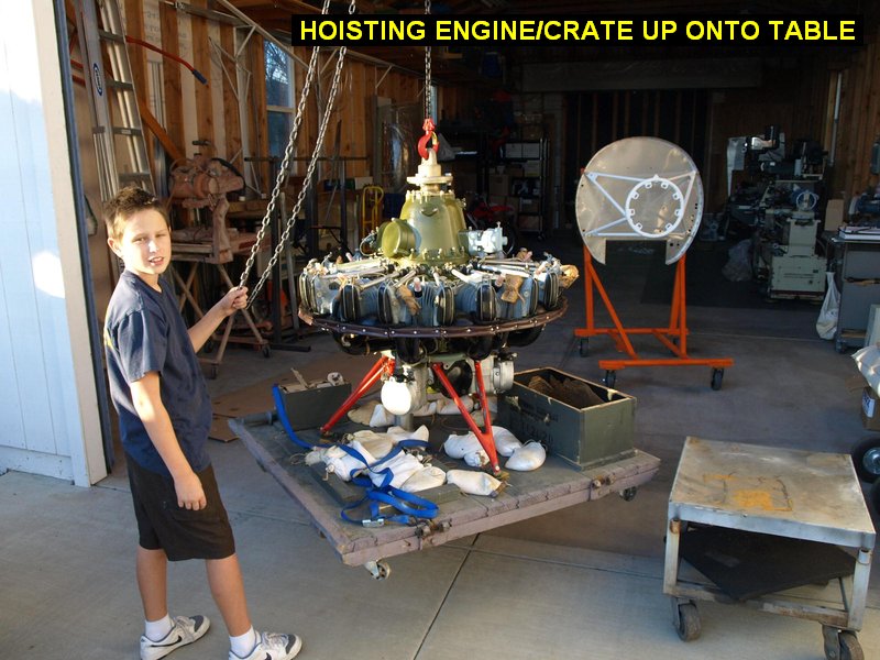
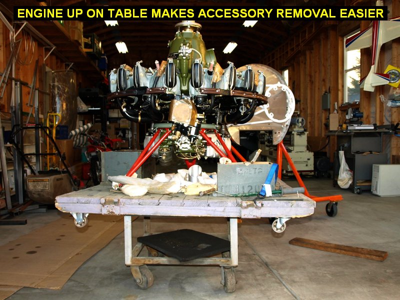
Borrowed a rolling transmission table from
Don and then lifted the engine and crate up onto it so I could work on the
engine easier. Took pics of the engine accessories in case I needed reference
later. |
 |
 |
| 01/16/09 |
4.0 |
1006.7 |
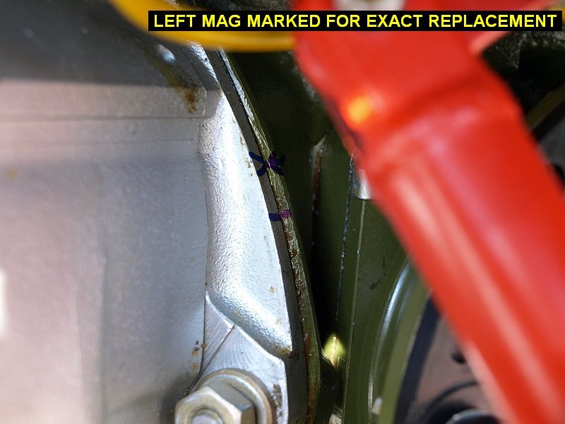
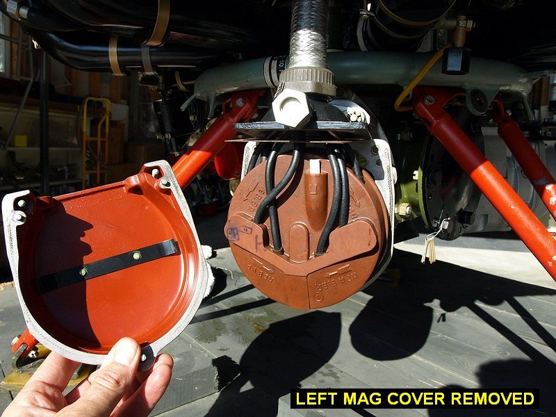
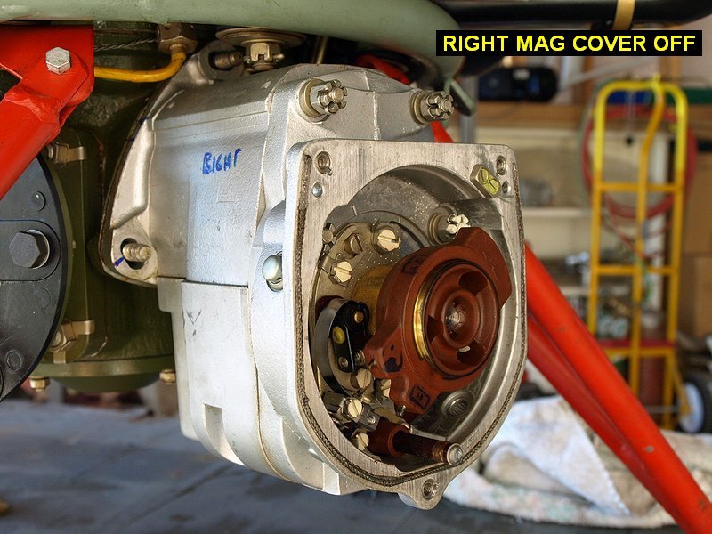
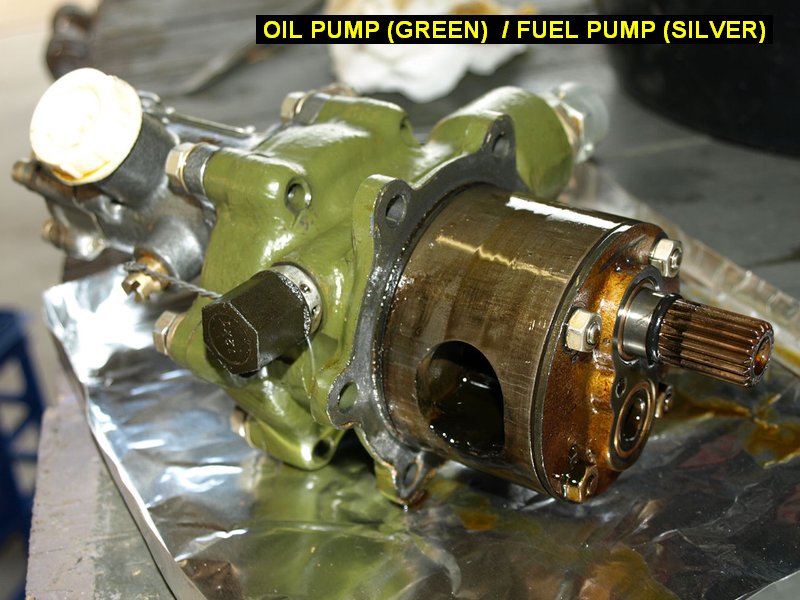
NOTE: DO NOT
ROTATE PROP SHAFT OR MAG COUPLINGS OR YOU WILL HAVE TO RE-TIME THE
IGNITION. Marked mags L and R with a sharpie pen, also
made numerous marks at base of each magneto to help ensure I can put them
back at the exact ignition timing the factory had them at. Removed mag
covers and rotor cap/wires, secured them up out of the way. Removed mags.
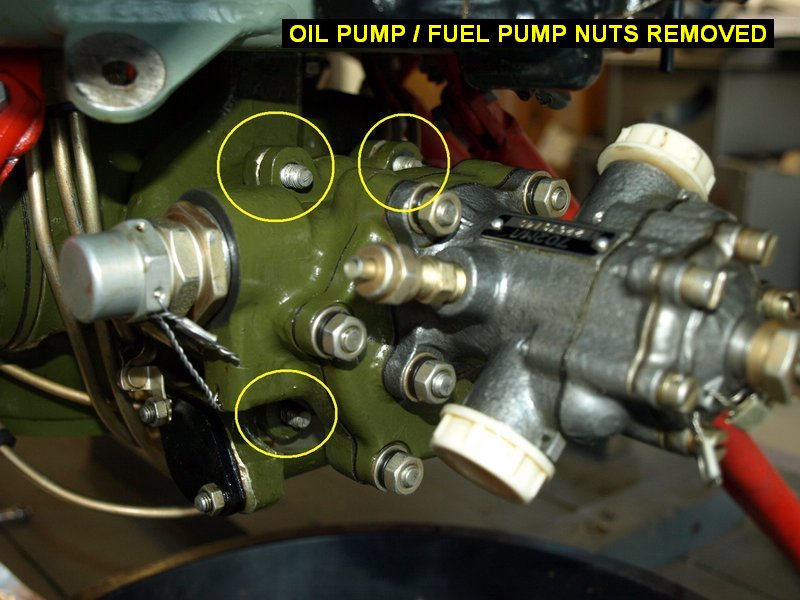
Removed the 6 nuts holding the oil pump / fuel pump tree, tried to remove
it, but wasn't sure how hard to hit it! Made posting on the google
group. Also see my Web
Page dedicated to moving the engine from crate to motor mount. |
 |
 |
 |
 |
| 01/17/09 |
2.5 |
1009.2 |
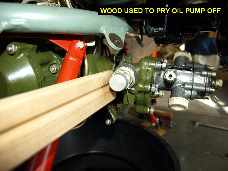
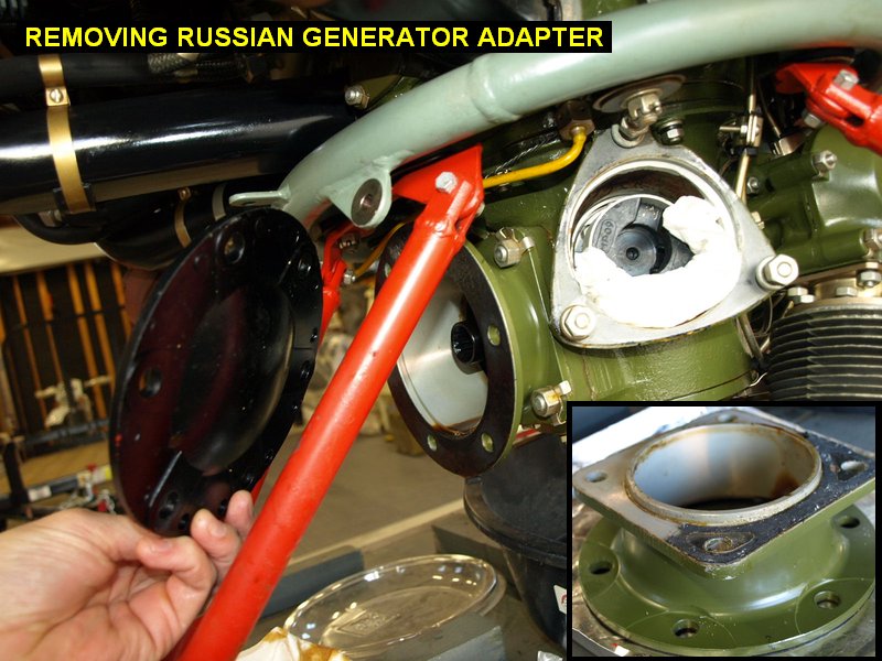
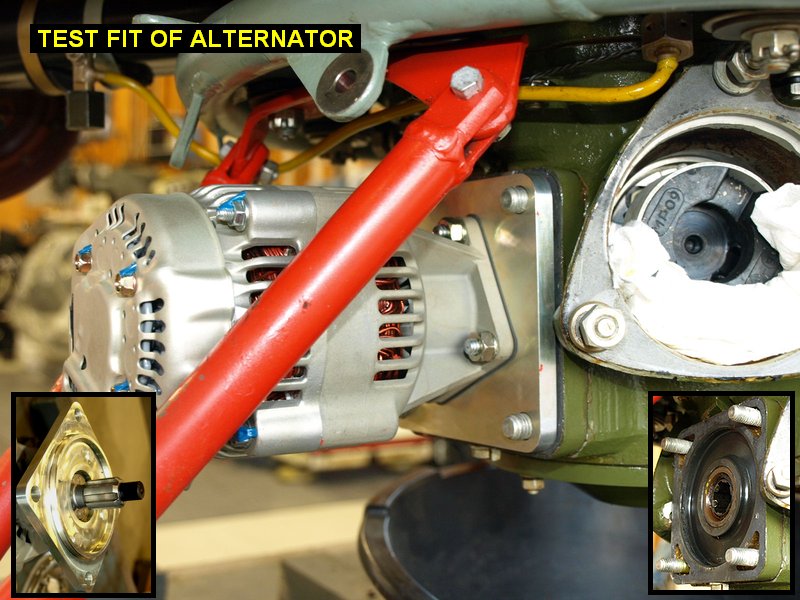
Found out that only
just the 6 nuts come off so I used a wood pry bar to slide the oil pump
tree off. Good thing I had a drain pan under it, a fair amount of oil came
out too. Next I removed the russian generator adapter and of course had to
test fit my B&C alternator, which fits good. All but one of the mag
gaskets broke so I'll have to find a source for those, or make some.
Web Page |
 |
 |
 |
 |
| 01/19/09 |
1.0 |
1010.2 |
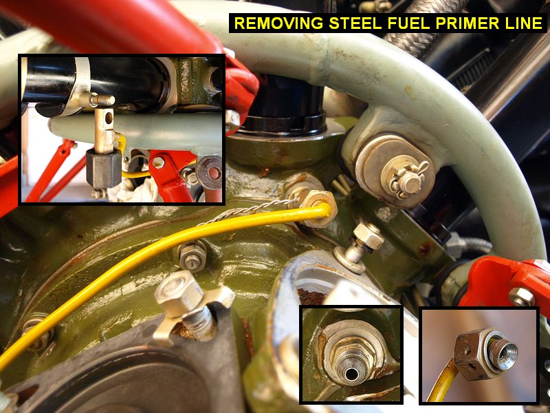
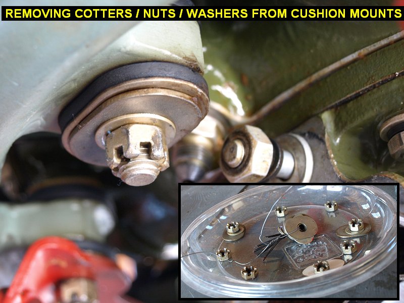
Removed steel primer line which
blocks the ring from coming off the engine. Removed the cotter pins,
nuts and washers from the 8 rubber cushion mounts. It took a long time to
take the cotter pins out with tight access. The cushion mounts are
supposed to be tightened to a certain thickness measurement which I
attempted to measure but I couldn't get a set of calipers in there. I took
my little torque wrench and measured what torque they were set at, and it
was amazingly low, 44 to 56 in�lbs! When I go to install the cushions on
the engine mount I will probably end up making some sort of tool to set
them at the right amount of compression. Didn't have enough time to pull
the motor off the crate and tackle the ring, but a test lift confirmed the
motor is loose! Web
Page |
 |
 |
| 01/23/09 |
4.0 |
1014.2 |
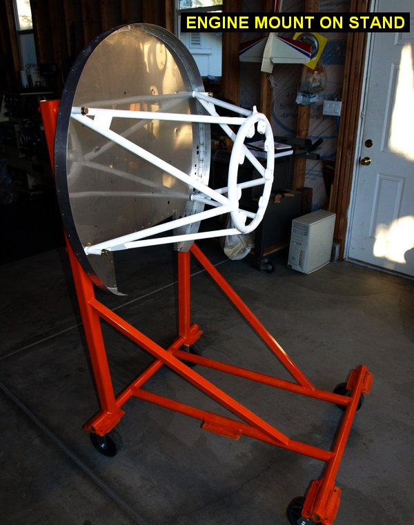
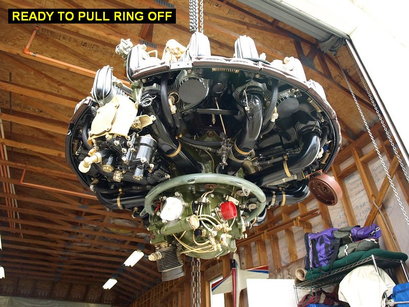
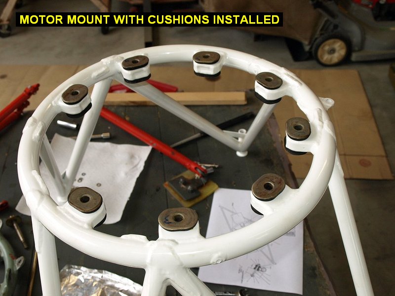
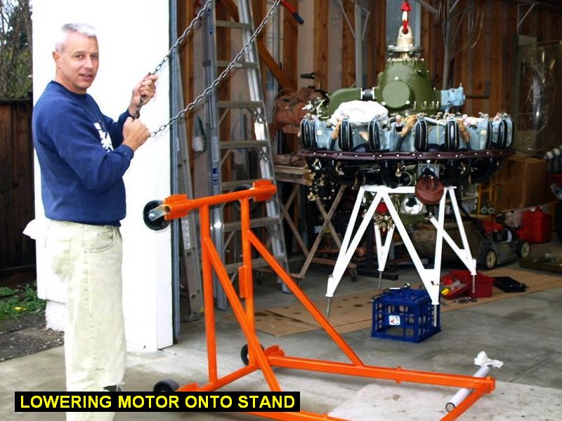
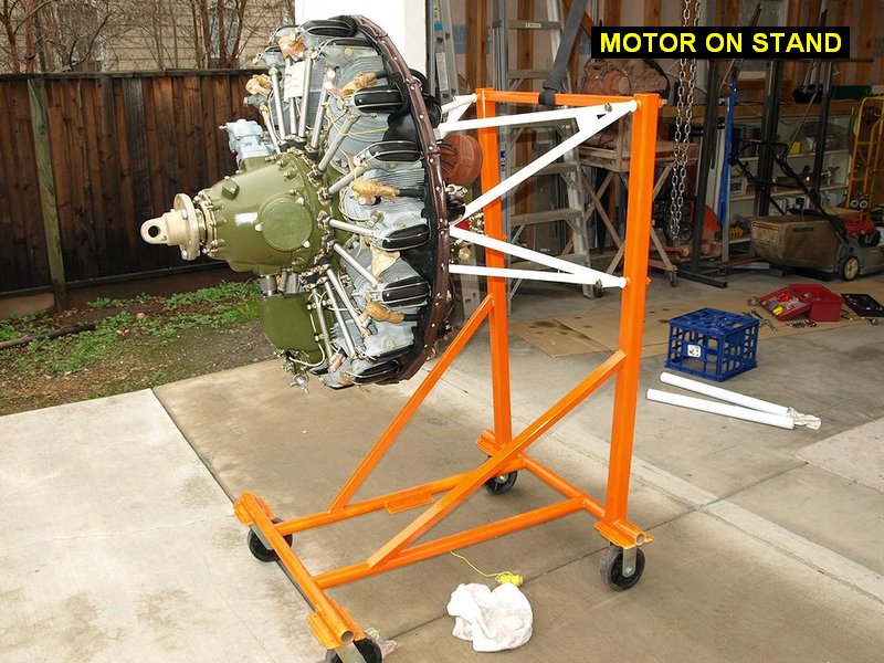
Don came over and we
hoisted up the motor, pulled the ring off. Worried about scratching the
powdercoat on the motor mount going back on we took one of the studs off
the left magneto pad, as well as the compressor. Transferred cushions over
to motor mount and installed it. Tightened cushions to 34.5cm per drawing
I got from Motorstar. We set the rolling stand on its back under the motor
and lowered the motor onto it. We then hoisted the stand up by the back
crossmember and tippedit onto its wheels. |
 |
 |
 |
 |
| 02/23/09 |
4.5 |
1018.7 |
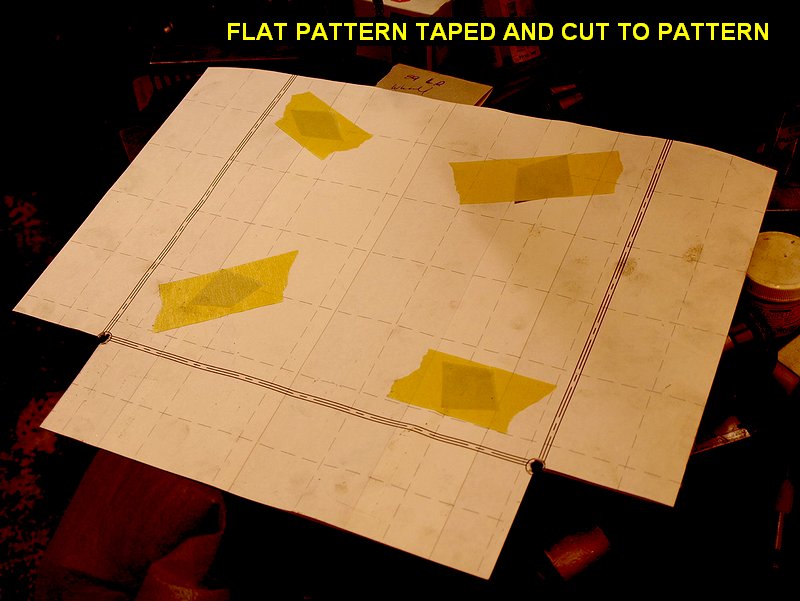
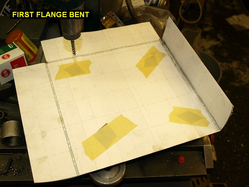
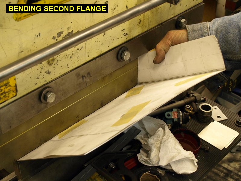
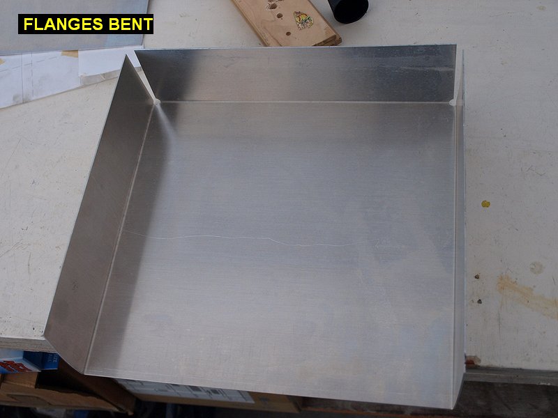
Made up a design
for a drawer for behind the front seat, printed out the flat pattern
for it and went over to Ken's. We cut it out and bent it up. |
 |
 |
 |
 |
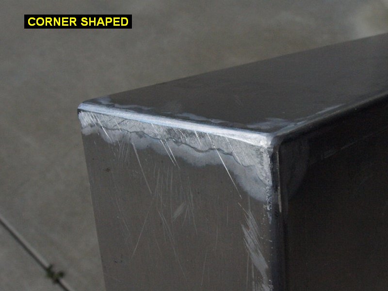
| 02/24/09 |
2.0 |
1020.7 |
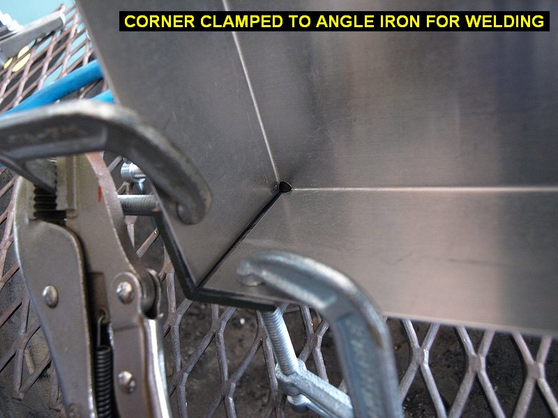
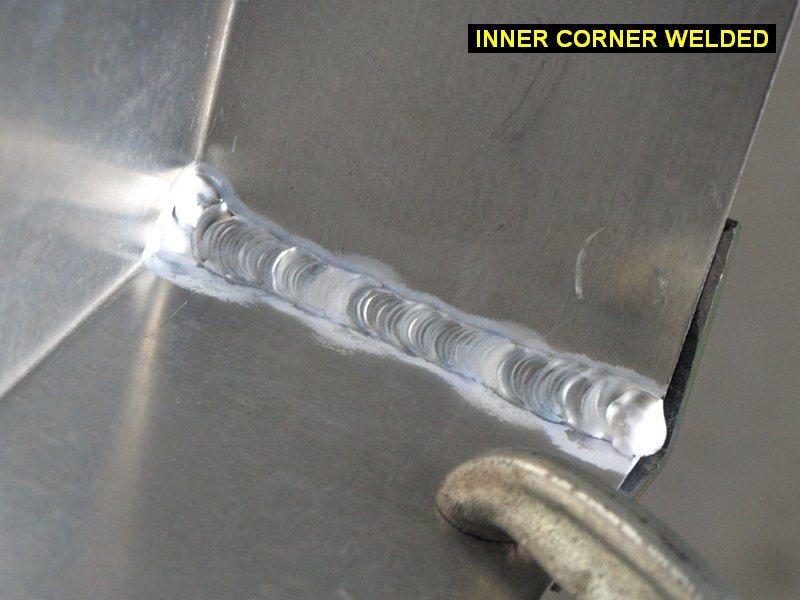
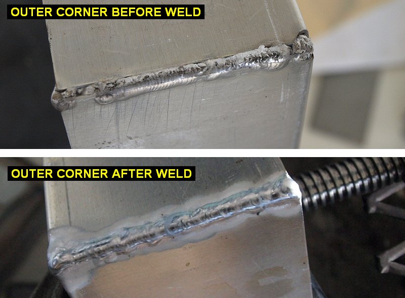
Adjusted the angles of the bends. Since the
corners had pretty large gaps, I got a short section of angle iron and
milled the inner corners square. I clamped the angle on the outside of the
corners to act like a mold. Welded up the inner corners, Then welded up
the outer corners. Filed the corners square. |
 |
 |
 |
 |
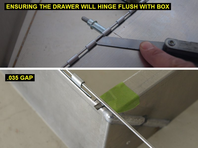
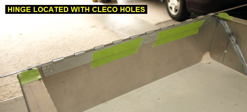
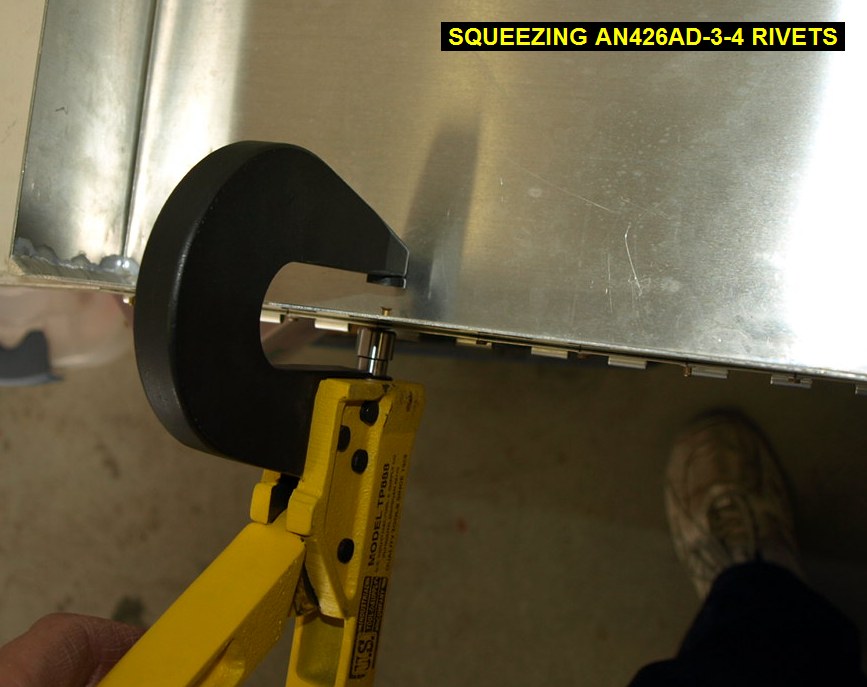
| 02/25/09 |
3.0 |
1023.7 |
Trimmed the opening of the box to fit the
drawer. Cut some MS20257-4 aluminum piano hinge to fit the bottom of the
drawer. Fit and riveted (AN426AD-3-4 solid aluminum countersink head rivet MS20426AD-3-4)
the hinge exposed so I could pull the pin
to remove the drawer anytime. |
 |
 |
 |
 |
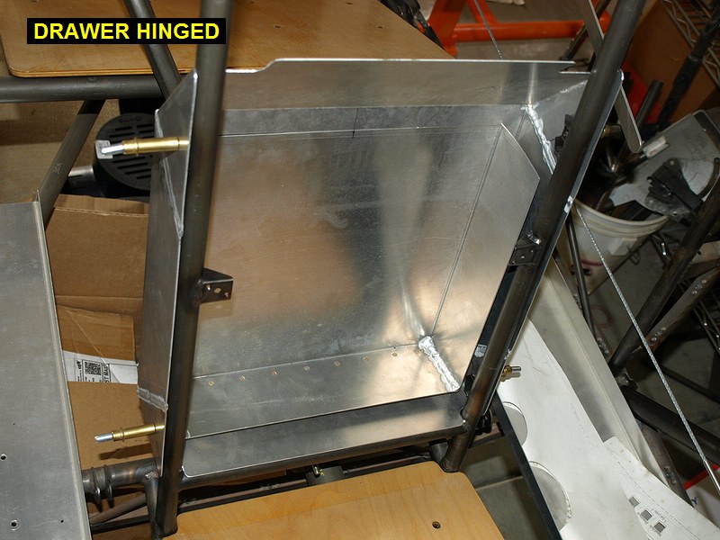
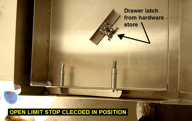
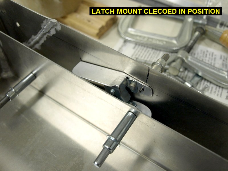
| 02/26/09 |
3.6 |
1027.3 |
Cut some small sections of 1/16" thick
3/4x3/4 aluminum angle for use as open limit stops to keep the drawer from
opening too far. Clecoed them in place withy two clecos each. I had
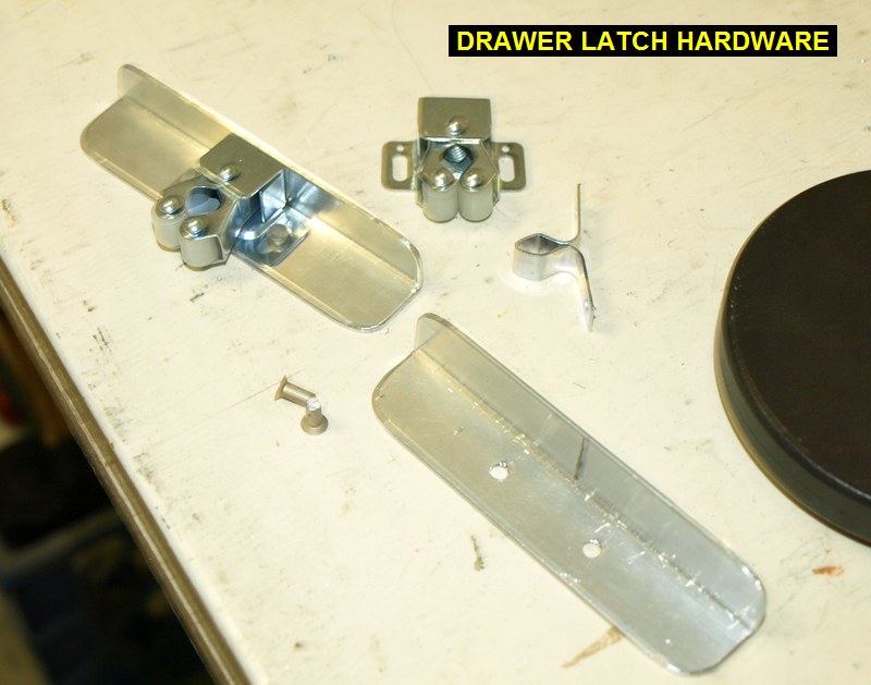
already bought a couple of point/roller drawer stops from my local
hardware store. I then cut two more smaller sections of the aluminum angle
to hold the rollers and riveted them them on. These rollers will be
mounted to the box sides, with the aluminum angles giving them more
support area compared to just attaching the rollers directly to the sides
of the box. The points that the rollers capture will be riveted to the
aluminum angles that are riveted to the drawer acting as limit stops. I
used some small sections of welding rod and safety wire to hold the drawer
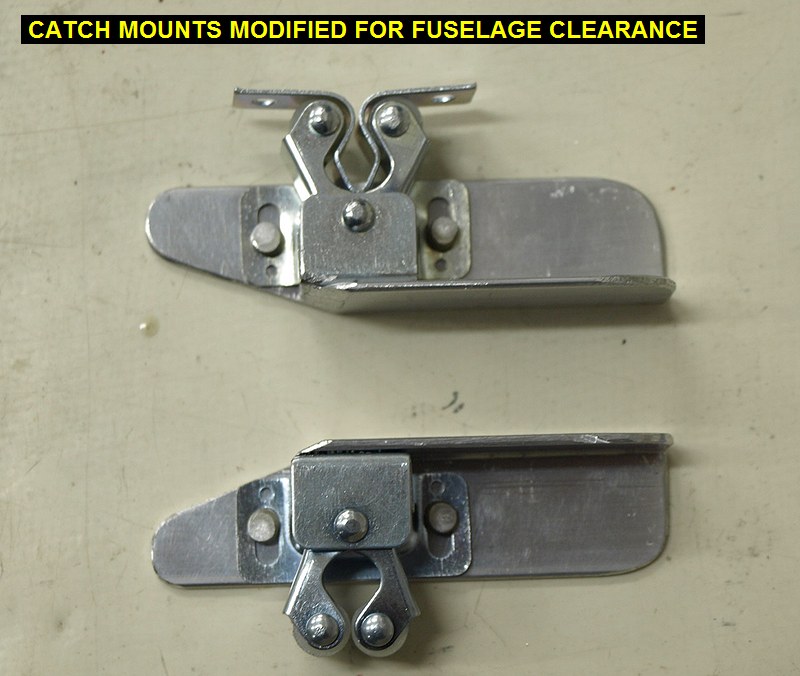
and box exactly flush during the fitment of the hardware. I soon
discovered that I had to trim the angles holding the rollers at a pretty
acute angle for it to work properly with the drawer and not hit the
fuselage's rear seat vertical tubes. |
 |
 |
 |
 |
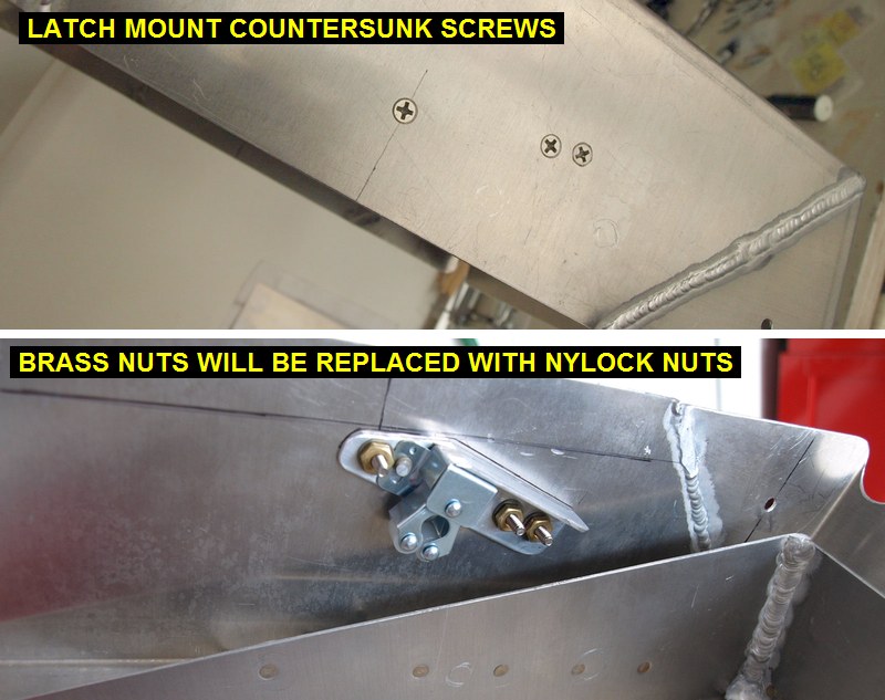
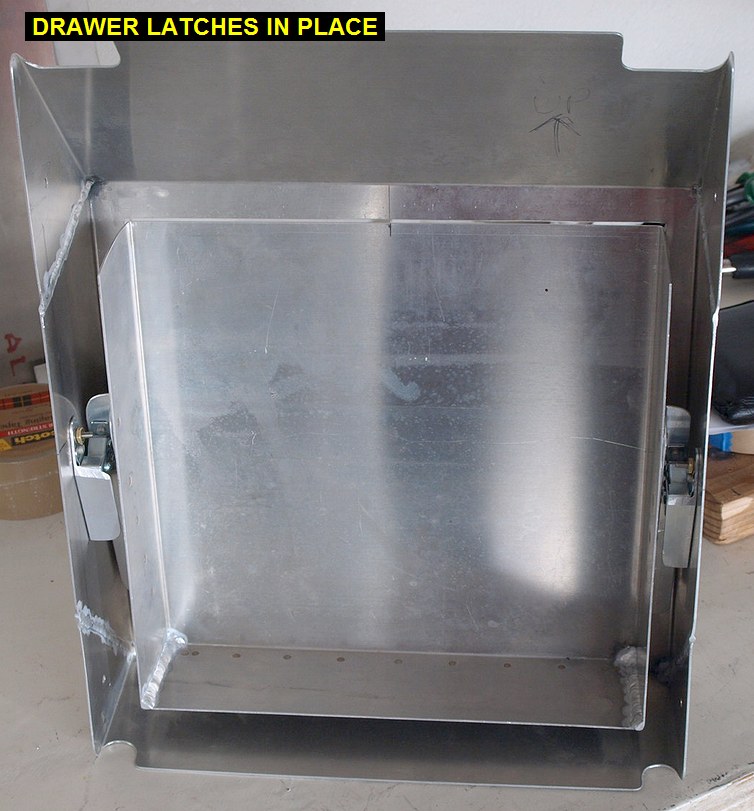
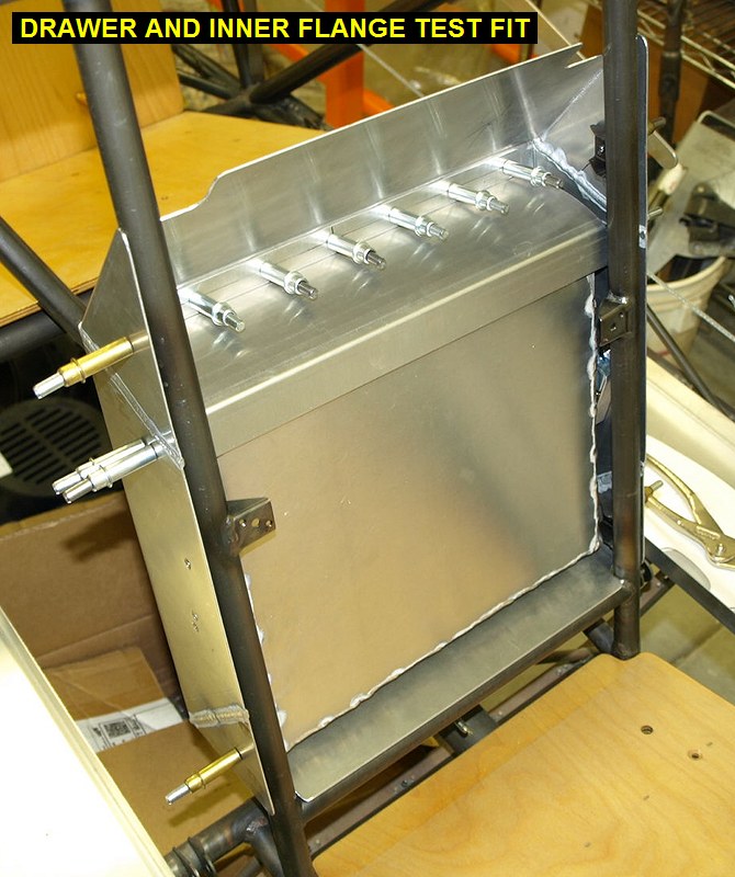
| 02/27/09 |
4.0 |
1031.3 |
After some test fitting of the box/drawer
onto the seatback tubes, I was able to determine where to mount the roller
assemblies. I couldn't mount them too high because they would hit the
fuselage tubes, or mount them down low, closer to the hinge would give
them more room, but also reduce their mechanical advantage to keep the
drawer shut during high G forces. I then located and riveted the points
onto the drawer open limit stops, Flush riveted (MS20426AD-3-4) the
drawer open limit stops onto the drawer sides, and I then drilled the
holes through the sides of the box and countersunk the holes so I could
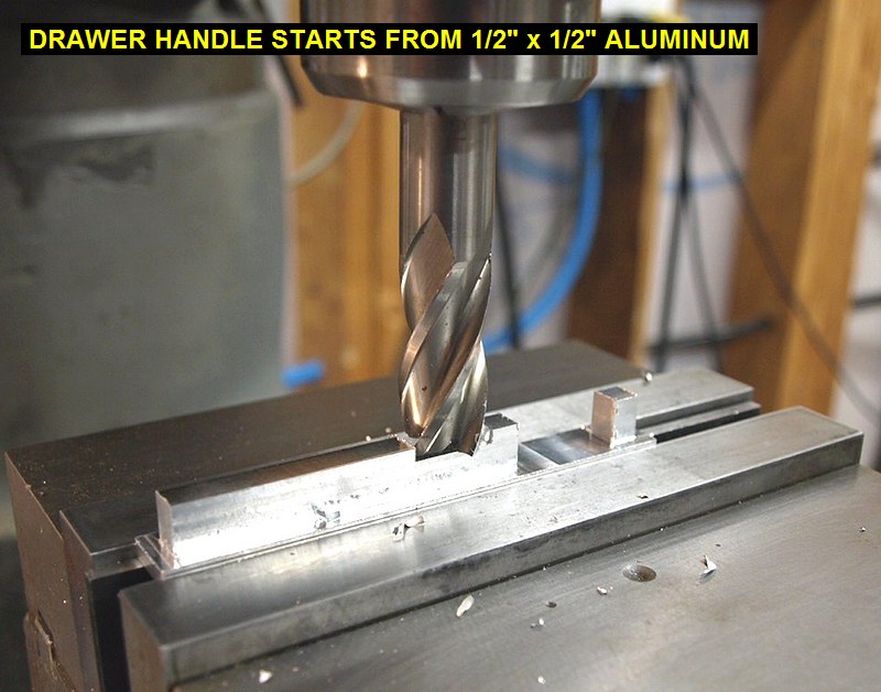
use flush #6 countersink stainless screws. The drawer latches have
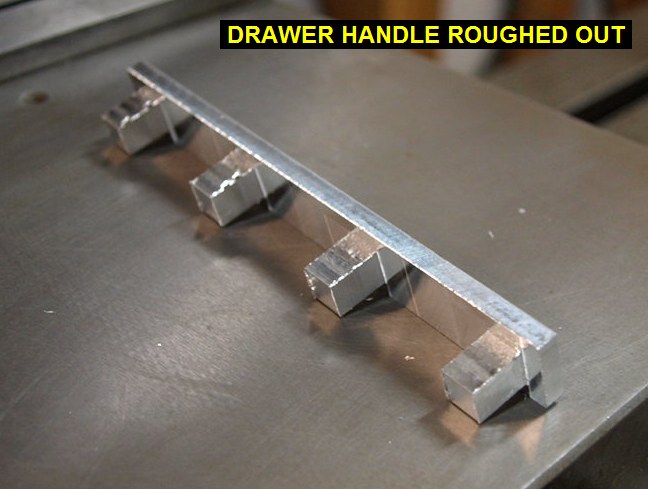
to be removable otherwise I cannot remove/install the drawer. Started work on a
machined drawer pull handle. I just didn't like anything I saw at the hardware
store. |
 |
 |
 |
 |
| 02/28/09 |
1.0 |
1032.3 |
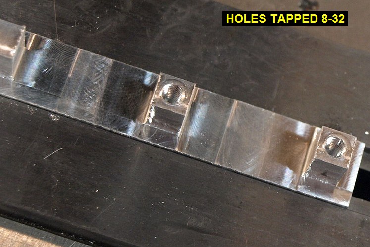
Finished milling the handle. Drilled and tapped the mounting holes
8-32. Cut some small chamfers on the
edges. Located and drilled the four holes to mount it on the front face of
the drawer. |
 |
 |
 |
| 03/01/09 |
2.5 |
1034.8 |
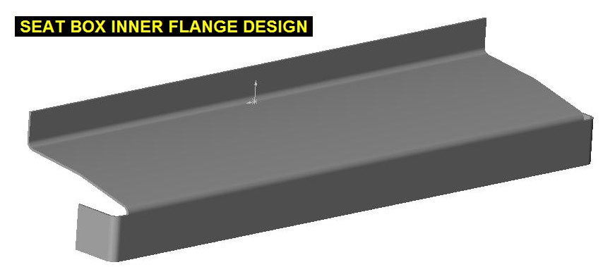
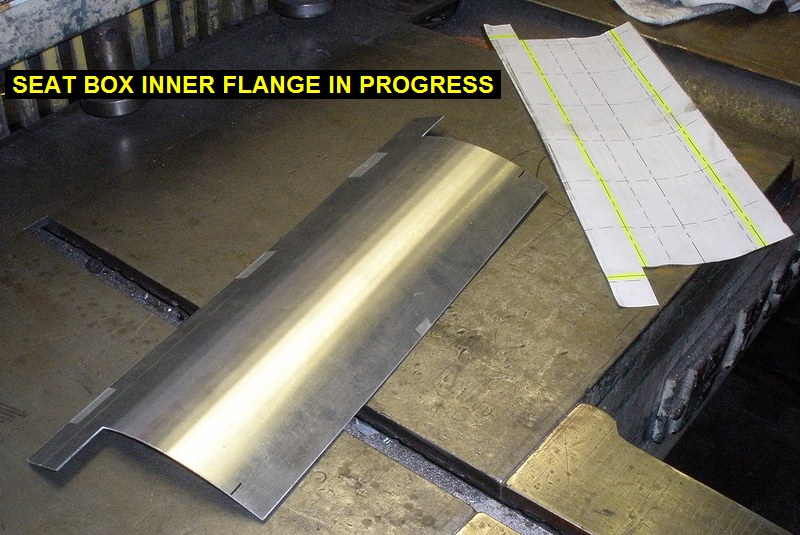
Drew up a flange to attach to the backside
of the seat box. This part will cover the top of the drawer when it's
closed so the contents stay in during negative G flight. See Seat
Box Inner Flange Flat Pattern |
 |
| 03/02/09 |
3.0 |
1037.8 |
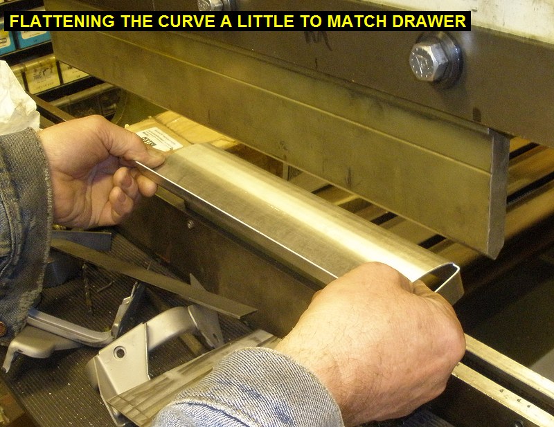
Printed out the flat pattern for the seat
box flange. Went over to Kens and cut it out and bent it up. It was quite
a bit of work to get the bend radius to match the drawer. Back home, I
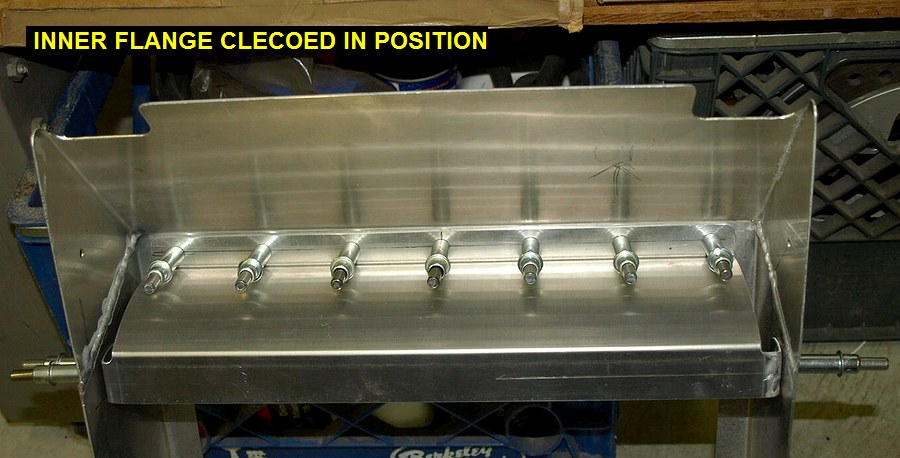
adjusted the bends to make it fit better. Drilled and clecoed it in place.
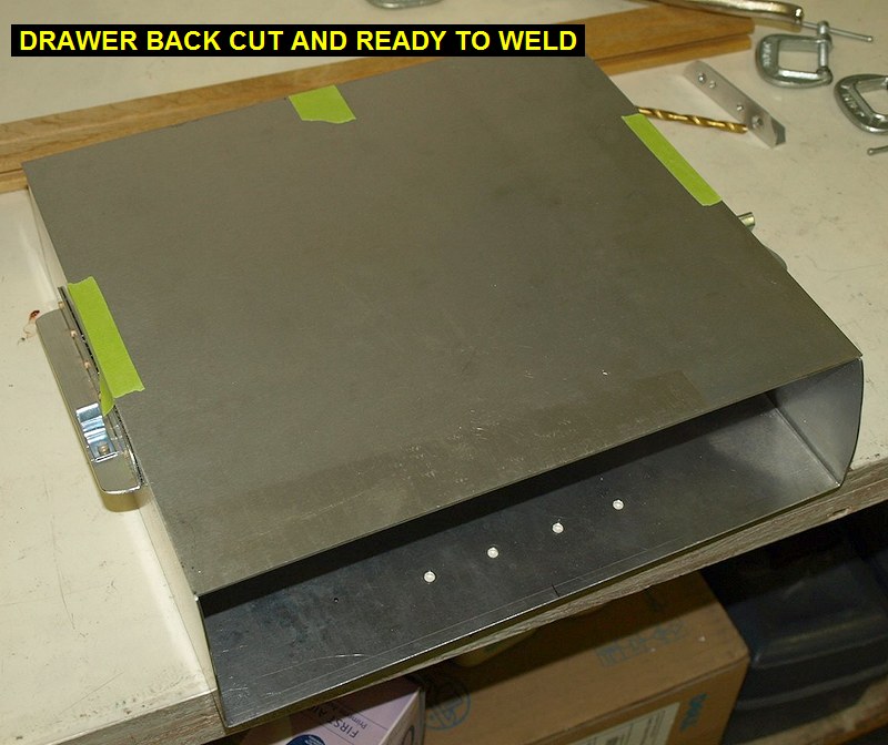
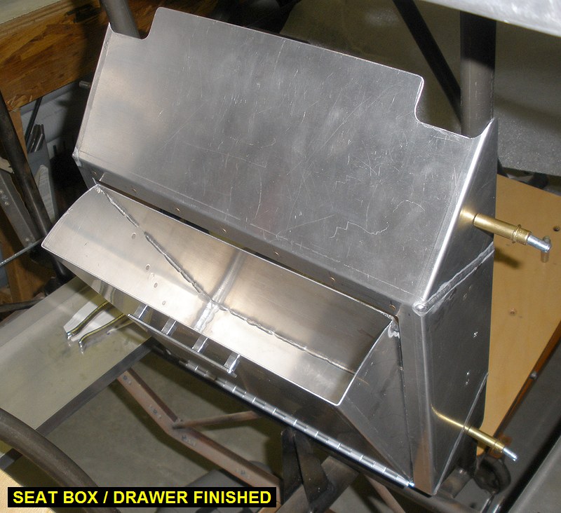
Cut and welded the top cover on the drawer. |
 |
 |
 |
 |
 |
 |
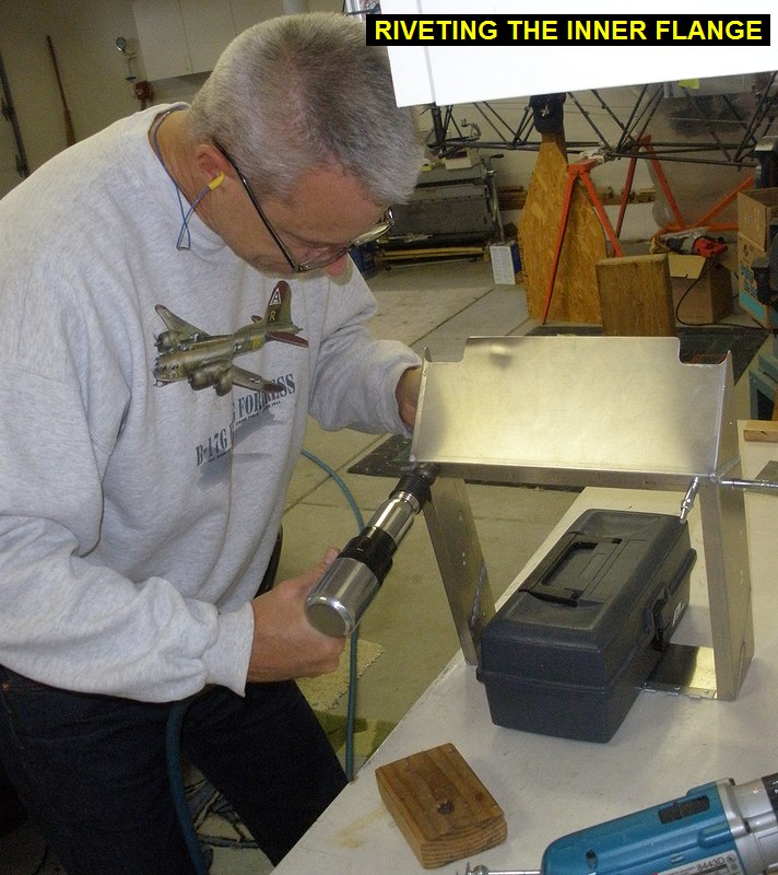
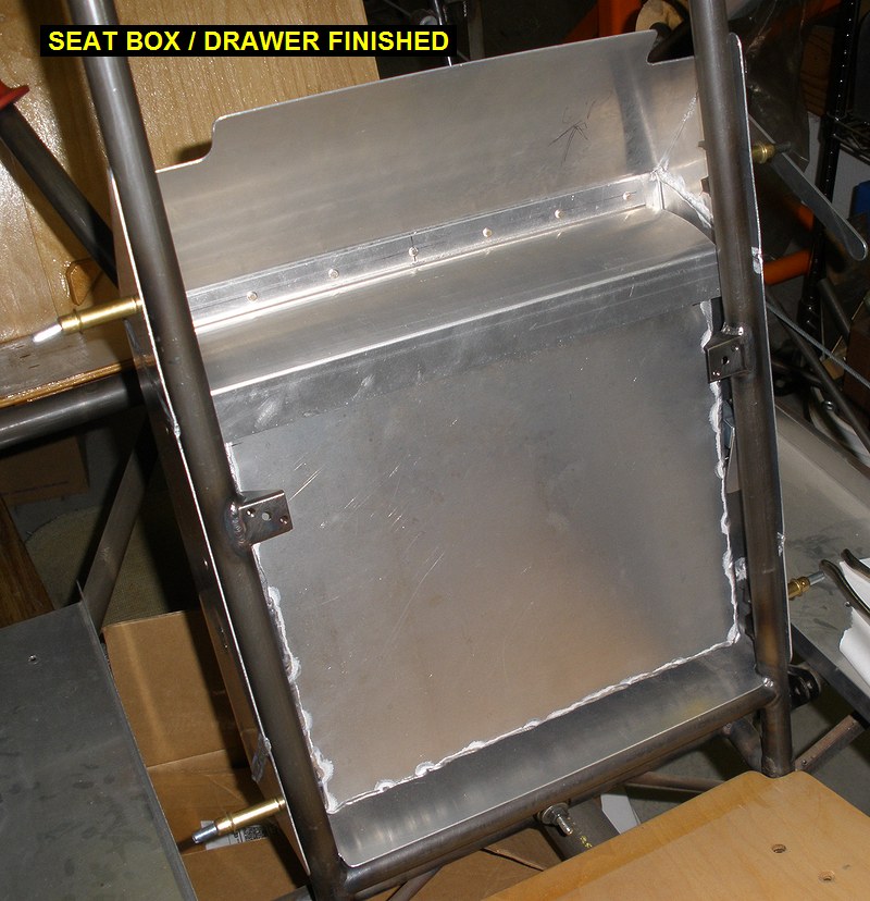
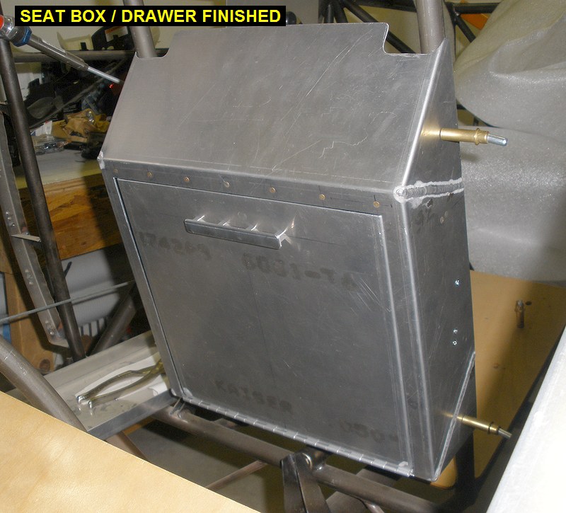
| 03/03/09 |
0.6 |
1038.4 |
Some minor adjustment of the drawer catches
and filing of the sharp edges. Riveted the inner flange in with
MS20426AD-3-4 rivets. Box / drawer is now ready for paint. Again
for reference the files to build this are here: Seat
Box Flat Pattern Drawer
Flat Pattern Inner Flange Flat Pattern |
 |
 |
 |
 |
| 03/21/09 |
3.0 |
1041.4 |
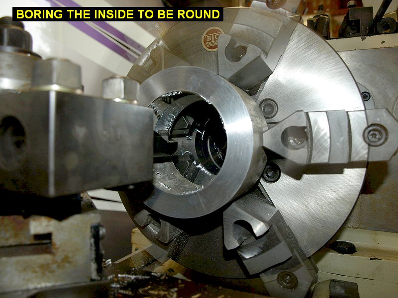
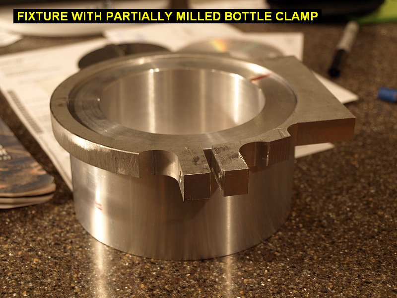
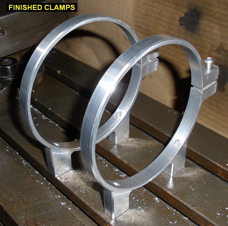
Decided to make the air
bottle clamps lighter. At the start of this they weighed 220 grams
each, quite heavy considering they are only holding a 3 lb bottle. I first
milled the bases of the clamps down a bit. I then borrowed a rotary table from Ken.
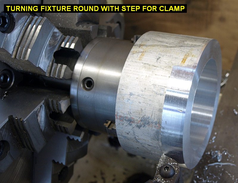
I also took a 5" diameter round of aluminum and made a cylindrical
fixture to hold the clamps on the rotary table. On the lathe, I first I
had to cut the ends square since the band saw leaves the ends anything but
square. I then bored out the inside to be round |
 |
 |
 |
 |
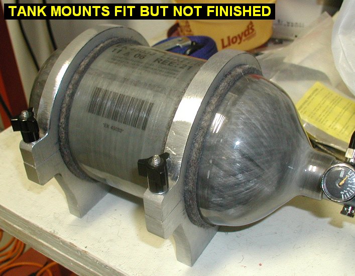
| 03/23/09 |
7.0 |
1048.4 |
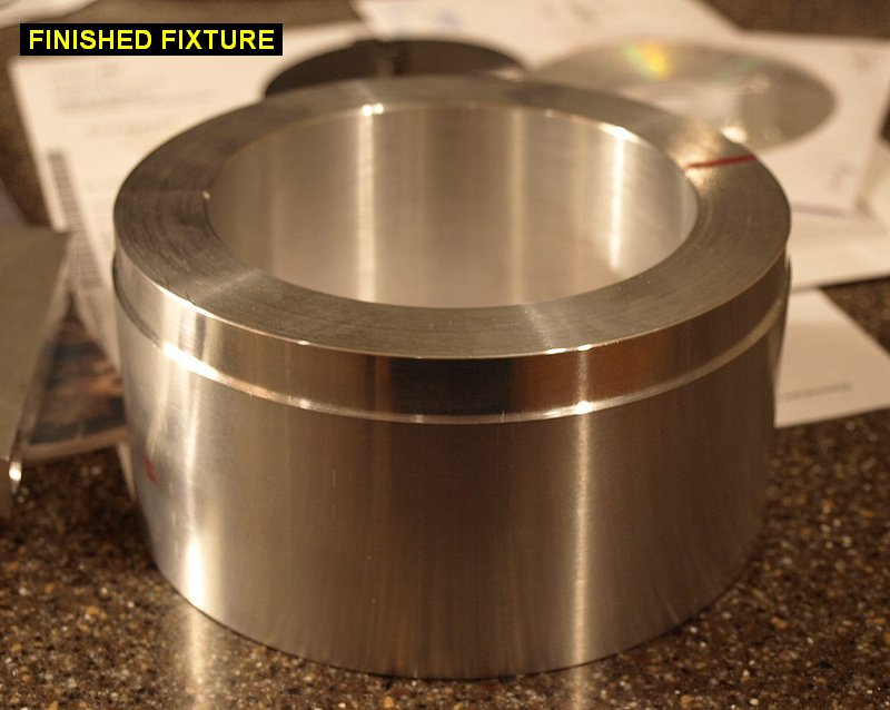
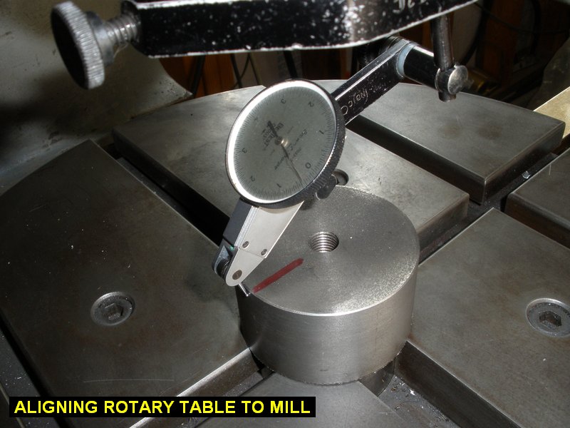
Over at Don's we cut
a rectangular piece of steel to clamp the fixture to the rotary table.
Back home I bolted the rotary table to the bridgeport, and then using a
dial indicator, made the axis of rotation coincidental with the tool
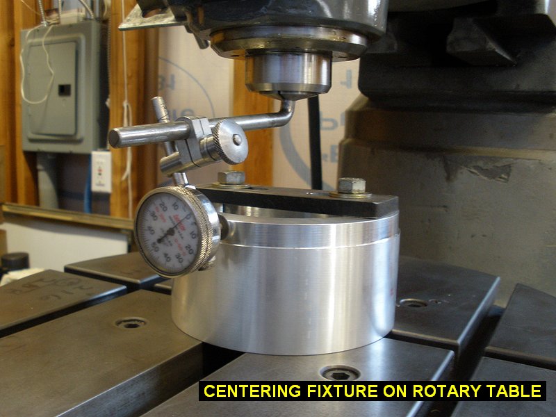
spindle of the mill. I then zeroed my dials there so I could put it back
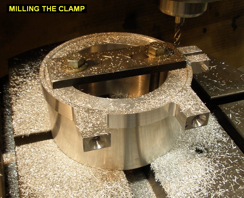
to center whenever needed. I then clamped the fixture to the rotary
table after centering it on the rotary table with a dial indicator. I then
spent many hours milling the clamps down thinner and thinner. To make them
look nice I put a countersink in the bridgeport and milled a chamfer on all the edges. They
now weigh about 104 grams each, less than half the weight before. |
 |
 |
 |
 |
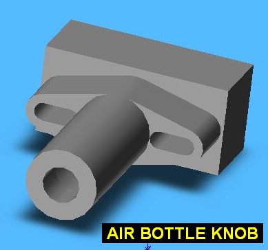
| 03/25/09 |
1.5 |
1049.9 |
Now I couldn't go and use those
cheap hardware store knobs on my new beautiful clamps, so I came up with a
design for ones made out of aluminum. More fun with the machines! Here's
the drawings for the knobs |
 |
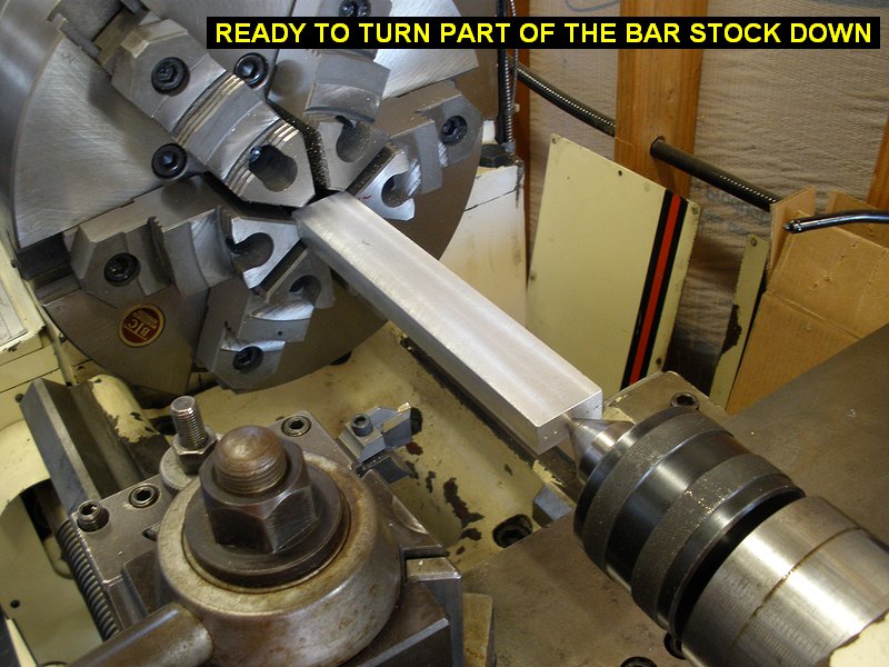
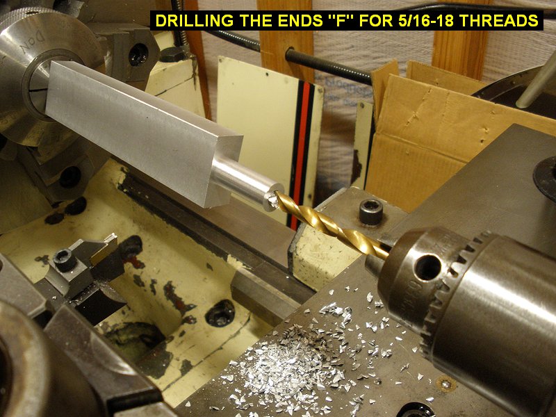
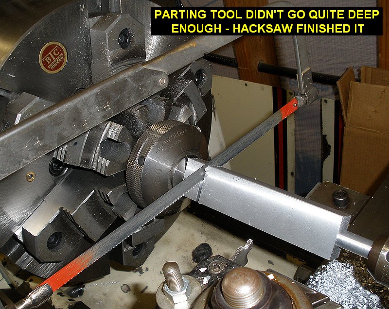
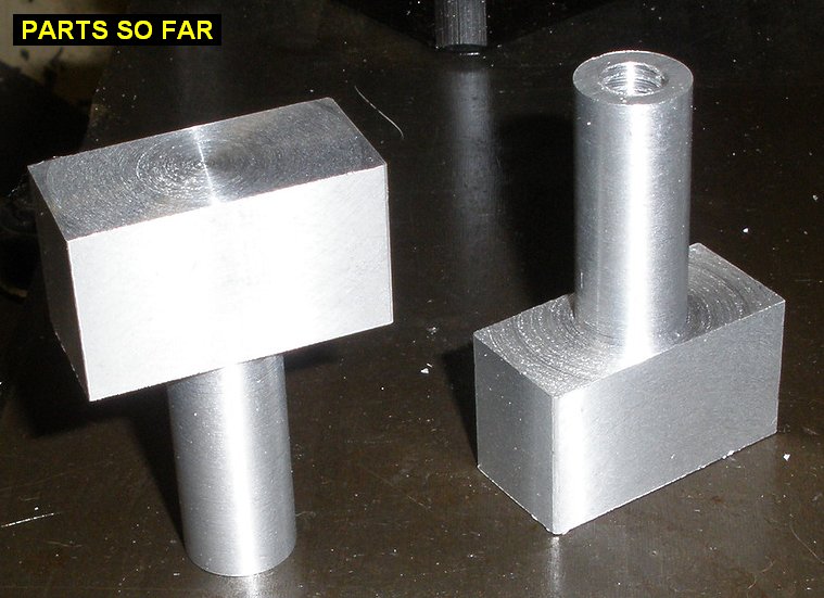
| 03/26/09 |
2.8 |
1052.7 |
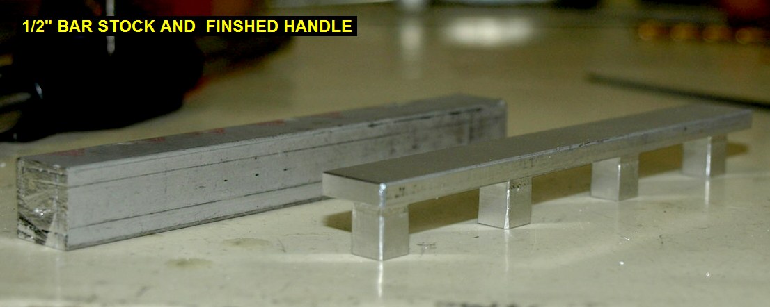
This project starts
with some bar stock aluminum. I spot drilled the ends of the bar to
work with the live center in my lathe tailstock. I then held the other end
of the bar with 2 of the 6 jaws of my chuck. After turning the end near
the live center down to .500" I swapped the bar around and turned the
other end down to .500". I then drilled the ends with a "F"
size drill and tapped them 5/16-18, which is the thread size required by
the steel thread inserts I plan to install later. I then cut the parts off
the bar. |
 |
 |
 |
 |
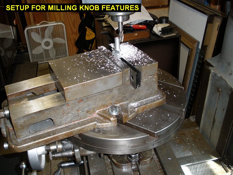
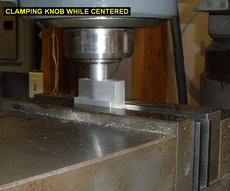
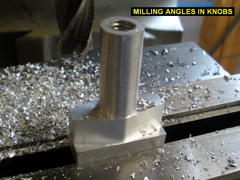
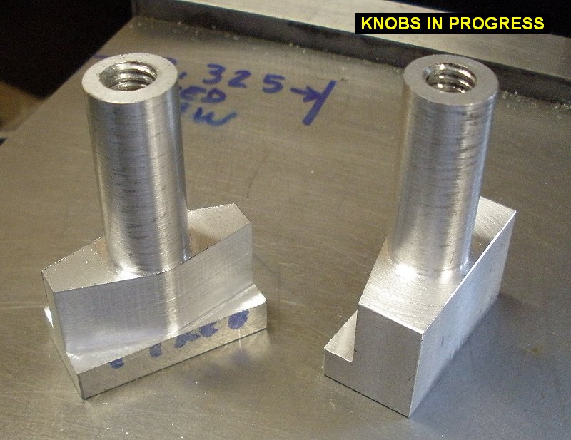
| 03/27/09 |
4.8 |
1057.5 |
Put my mill vise up
on the rotary table so I could mill the angle and radius features into the
knobs. Once I figured the correct table angle that made the knob bases
square with the milling machine it was easy to do the math and figure out
the two rotary table angles to mill the sides at. To make sure I had the
knob clamped in the vise at the center of the rotary table I zeroed it
with the milling machine, then put the 1/2" shaft in a 1/2"
collet in the bridgeport and clamped the vise with it all in alignment. I
then cut the angles in the knobs 3/4" deep. I got the the nice finish
by doing a "climbing" cut across one face, rotating the table
and cutting across the center of the knob, then continuing the cut across
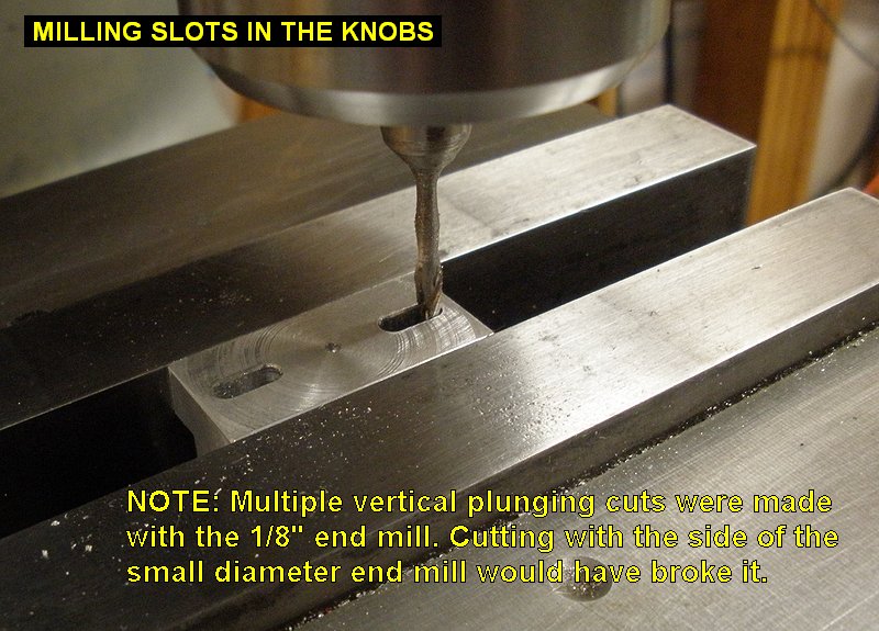
the last face. After doing the angles, I then flipped them over and milled
the 1/8" diameter slots using many incremental plunging cuts so as to
not side-load the 1/8 diameter end mill and break it. |
 |
 |
 |
 |
 |
 |
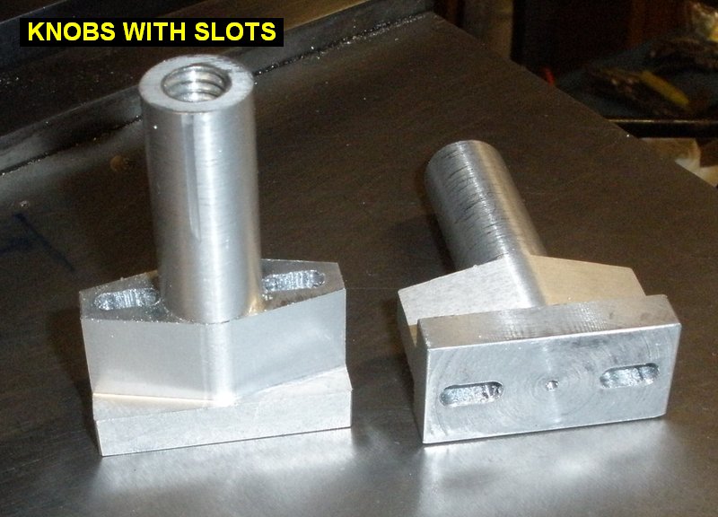
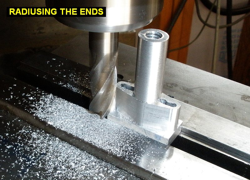
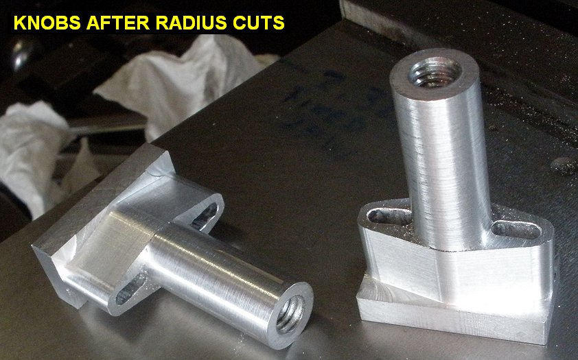
| 03/27/09 |
1.0 |
1058.5 |
Cut the radius in the ends of
the knobs. I clamped each knob in the vise with the outer end of the slot
centered on the rotary table, then moved table to set the cutting tool at
a larger than desired radius. I then figured out what angles to rotate the
table from-to while cutting and gradually reduced the radius until it
matched the side angles I cut yesterday. |
 |
 |
| QTR TOTAL |
58.3 |
|
|
1ST QTR 2009
|
•
•
•
|


